
User Manual


73
T89C51AC2
Rev. B – 19-Dec-01
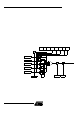
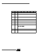
15.6 High Speed Output
Mode
In t his mode the CEX output (on port 1) associated w ith the PC A module will toggle
each time a match occurs between the PCA counter and the module’s capture registers.
To activate t his mo de the TO G , M AT, an d EC O M bits in the mo d ule ’s CC APMn SF R
must be set.
Figure 34. PC A High speed Output Mode
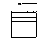
15.7 Pulse Width
Modulator Mode
Al l the P C A mod ules can be used as PWM output s . The out put f requenc y depends o n
the sou rce fo r the PCA timer. All the m odules wil l have the s ame ou tput frequ ency
because they all share the PCA timer. Th e duty cycle of each module i s indep endent ly
va riable u s ing th e modul e’s ca pt ure reg ist er CCAP Ln. When the v alue of the P CA CL
SF R is less t han the value in the m odule’s CCAPLn SFR the output will be low, when it
is equal to or greater than it, t he output wi ll be high. When CL overflows from FF to 00,
CCAPLn is reloaded with the value i n CCAPHn . the allows the PWM to be updated with-
out glitches. The P WM and ECOM bits in the m odule’s CCAP Mn register mus t be set to
enable the PWM mode.
CH CL
CCAPnH CCAPnL
ECOMn
CCAPMn,n=0to4
0xDA to 0xDE
CAPNn MATn TOGn PWMn ECCFnCAPPn
16 bit comparator
Match
CF CR
CCON
0xD8
CCF4 CCF3 CCF2 CCF1 CCF0
PCA IT
Enable
CEXn
PCA counter/timer
“1”“0”
Write to
CCAPnL
Reset
Write to
CCAPnH