
User Manual


71
T89C51AC2
Rev. B – 19-Dec-01
Each module in the P CA has a special f unc tion regi ster associated with it (CCAPM 0 for
module 0 ...). The CCAP M0:4 registers cont ain the bits that cont ro l the mode that each
module w ill operate in.
• The ECCF bit enables the CCF flag in the CCON regist er t o generate an interrupt
when a match o r compare occurs i n the associate d m odule.
• The PWM bit enables the pulse width m odulation mode.
• The TOG bit when set ca us es th e CEX output assoc iated with the module to toggle
when there is a match between the PC A counter and the module’s capt ure/com pare
register.
• The match bit M AT when s et will c ause the CCFn bit in the CCON register to be set
when there is a match between the PC A counter and the module’s capt ure/com pare
register.
• The two bi ts CAPN a nd CAPP in CCAPMn register det ermine the edge that a
capture input will be act ive on. The CAPN bit enables the negati ve edge, and the
CAPP bit enables the positive edge. If both bits are set both edges wi ll be enable d.
• The bit ECO M in CCAP M register wh en set enable s the comparat or f unc tion.
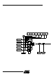
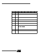
15.3 PCA Interrupt Figure 31. PCA Interrupt S y stem
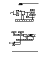
15.4 PCA Capture Mode To use one of the P CA modul es in ca pture mode either one or both of the CCAPM bits
C APN a nd CAP P for that module m ust be set. T he external CEX input for the m odule
(on port 1) is s ampled f or a transition. When a valid transition oc cu rs t he PCA hardware
loads the value of the PCA counter registers ( CH and CL) into the module’s capture reg-
isters (CCAPnL and CCAPnH). If the CCFn bit fo r t he m odule in the CCO N SFR and the
ECCF n bit in the CCAPMn SFR a re set then an interrupt will be generated.
CF CR
CCON
CCF4 CCF 3 CCF2 CCF1 CCF0
Module 4
Module 3
Module 2
Module 1
Module 0
PCA Timer/Counter
ECCFn
CCAPMn.0
To Interrupt
EA
IEN0.7
EC
IEN0.6
ECF
CMOD.0