
User Manual


70
T89C51AC2
Rev. B – 19-Dec-01
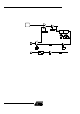
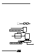
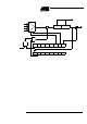
Figure 30. PCA Timer/Counter
The CMOD register includes three additional bits associated with the PCA.
• The CIDL bit which allows the PCA to st op during idle m ode.
• The WDTE bit which enabl es or disables the watchdog f unc tion on module 4.
• The ECF bit which wh en set caus es an interrupt and the P C A ov erf low flag CF in
CCON regist er to be set when the P CA timer o ve rflows.
The CCON register contains the run control bit for the PCA and the flags for the PCA
timer and e ach module.
• The CR bit m ust be s et to run t he PCA. T he PCA is shut off by clearing this bit.
• The CF bit is set when the PCA counter overflows and an interrupt will be generate d
if the ECF bit in CMOD register is s et. The CF bit c an onl y be cleared by software.
• The CCF0:4 bits are the flags for t he m odules (CCF0 for module0...) and are set by
hardware w hen either a match or a capture occurs. These f lags also can be cleared
by software.
15.2 PCA modules Each one of the five compare/capture modules has six possible functions. It can
perform:
• 16-bit Capture, positive-edge triggered
• 16-bit Capture, negative-edge triggered
• 16-bit Capture, both positive and negative-edge triggered
• 16-bit Software Timer
• 16-bit High Speed Output
• 8-bit Pulse Width Modulator.
In addition module 4 c an be used as a Watchdog Timer.
CIDL CPS1 CPS 0 ECF
It
CH CL
16 bit up/down count er
To PCA
modules
FPca/6
FPca / 2
T0 OVF
P1.2
Idle
CMOD
0xD9
WDTE
CF CR
CCON
0xD8
CCF4 CCF3 CCF2 CCF1 CCF0
overflow