
User Manual

69
T89C51AC2
Rev. B – 19-Dec-01
15. Programmable
Counter Array PCA
The PCA provides m ore tim ing capabilities with less CP U intervention than the standard
timer/c ounte rs. Its advantages in c lude reduc ed soft ware overhead and impro ve d accu-
racy. The PCA consists of a dedicated timer/cou nt er which s erv es as the t im e base for
an array of five compare/capture modules. Its clock input can be programmed to count
any of the fo llowing signals:
• PCA clock frequency / 6 (see “clock” sec tion)
• PCA clock frequency / 2
•Timer0overflow
• External input on ECI (P1.2)
Each com pare/capture module s can be programmed in any one of the f ollowing modes:
• rising and/or fall ing edge c apture,
• so ftware timer,
• high-speed output,
• pulse width modulator.
Modul e 4 can also be programm ed as a watchdog tim er. see Section "PCA Wa tchdog
Timer".
W hen the c ompare/c apture modules are programmed in c apture mode, software timer,
or high speed output mode, an interrup t can be generated when the module executes its
function. A ll f ive modules plus the PCA timer overf low share one interrupt vec tor.
The PCA timer/counter and compare/capture modules share Port 1 for external I/Os.
Thesepinsarelistedbelow.IftheportisnotusedforthePCA,itcanstillbeusedfor
standard I/O.
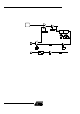
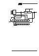
15.1 PCA Timer The PCA ti mer is a common t im e bas e for all five modules (see Fig ure 30). Th e ti mer
coun t source is determined from the CPS1 and CPS0 bits in the CMOD SFR (see Table
8) and can be programmed to run at:
• 1/6 t he PCA c lock frequenc y.
• 1/2 t he PCA c lock frequenc y.
• the Timer 0 overf low.
• the input on th e EC I pin (P1.2).
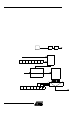
PCA component External I/O Pin
16-bit Counter P1.2 / ECI
16-bit Module 0 P1.3 / CEX0
16-bit Module 1 P1.4 / CEX1
16-bit Module 2 P1.5 / CEX2
16-bit Module 3 P1.6 / CEX3
16-bit Module 4 P1.7 / CEX4