
User Manual


60
T89C51AC2
Rev. B – 19-Dec-01
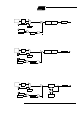
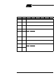
Figure 27. Aut o-Reload Mode Up/Down Counter
13.2 Programmable
Clock-Output
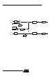
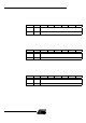
In c lock-o ut mode, tim er 2 operat es as a 50%-dut y - cycle, p r ogramm able clock genera-
tor (See F igure 28). T he input clock increments TL2 at frequency F
OSC
/2. The timer
repeatedly counts to overflow from a loaded value . At overfl ow, the contents of RCAP 2H
and RCAP2L registers are load ed in to TH2 and T L2. In this mode, timer 2 o ve rflows do
not generate interrupts. The formula gives the clock-out frequenc y depending on the
system oscillator frequency and the value in the RCAP2H and RCAP2L registers:
For a 16 MHz system clock in x 1 mode, timer 2 has a programmable frequency range of
61 Hz (F
OSC
/2
16)
to 4 MHz (F
OSC
/4). The generated clock signal is brought out t o T2 pin
(P1.0).
Timer 2 is programme d for t he clock-out mode as follows:
• Set T2OE bit in T2MOD register.
• Clear C/T 2
bit in T2C ON regist er.
• Dete rmin e the 16 -bit reload value from the formul a and ent er it in RCAP2H/RCAP2L
registers.
• En ter a 16-bit initial value in timer registers TH2/TL2. It can be the sam e as the
reload value or different depending on the application.
• To start the timer, set T R 2 run control bit in T2CON register.
(DOWN COUNTING RELOAD VALUE)
TF2
T2
EXF2
TH2
(8-bit)
TL2
(
8-bit)
RCAP2H
(8-bit)
RCAP2L
(8-bit)
FFh
(8-bit)
FFh
(8-bit)
TOGGL E
(UP COUNTING RELOAD VALUE)
TIMER 2
INTERRUPT
:6
T2CONreg
T2CONreg
T2EX:
1=UP
2=DOWN
0
1
CT/2
T2CON.1
TR2
T2CON.2
FT2
CLOCK
see section “Clock”
C lo ck OutFr eque ncy–
FT2clock
4 65536 RCAP2H– RCAP2L⁄()×
--------------------------------------------------------------------------------------------
=