
User Manual


54
T89C51AC2
Rev. B – 19-Dec-01
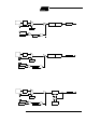
12.3.1 M ode 0 (13-bit Timer) Mode 0 configures Timer 1 as a 13-bit Timer, wh ich is set up as an 8-bit Timer (TH1 reg-
ist er) with a m odulo-3 2 pres c aler im plemented with the lower 5 bits of the TL1 regist er
(see Figure 22). The u pper 3 bits of TL1 register are ignored. Presc aler overflow i nc re-
ments TH1 register.
12.3.2 M ode 1 (16-bit Timer) Mode 1 configure s Timer 1 a s a 16-bit Tim er with TH1 and TL1 regist ers connect ed in
cascade (see Figure 23). T he selected input i nc rements TL1 register.
12.3.3 Mode 2 (8-bit Tim er with
Auto-Reload)
Mode 2 co nfigures T imer 1 as an 8-bit Timer (TL1 register) with automatic reload from
TH1 regist er on overflow (s ee Figure 24). TL 1 overflow s et s TF1 flag in TCON registe r
and reloads TL1 with the c ontents of TH1 , w hich is p reset by softw are. The reloa d
leaves TH1 unchanged.
12.3.4 Mod e 3 (Halt) Pla cing Timer 1 in m ode 3 c ause s it to h alt and hold its c ount. This can be used to halt
Timer 1 when TR1 run control bit is not available i.e. w hen Timer 0 is in mode 3.
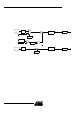
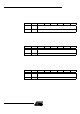
12.4 Interrupt Each Timer h andles one inte rrup t source that is the timer ove rflow flag TF0 or TF1. T his
flag is set every tim e an ov erflow oc c urs. Flags are cleared when v ec t oring to the Timer
interrupt routine. Interrupts are enabled by setting
ETx bit in IEN0 register. This assumes
interrupts are globall y enabled by s etting EA bit in IEN0 reg ister.
Figure 26. T imer Interru pt System
TF0
TCON.5
ET0
IEN0.1
Timer 0
Interrupt Request
TF1
TCON.7
ET1
IEN0.3
Timer 1
Interrupt Request