
User Manual


53
T89C51AC2
Rev. B – 19-Dec-01
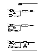
12.2.4 Mode 3 (Two 8-bit
Timers)
Mode 3 con figures T imer 0 s uch that reg ist ers TL0 and TH0 operate as separa te 8-bit
Timers (s ee Figure 25). This mode is prov ided for ap plications requiring an additional 8-
bit Timer or Count er. TL0 uses the Timer 0 cont rol bits C/ T0# and GATE0 in TMOD reg-
ister, and TR0 and TF0 in TCON register in the normal manner. TH0 is locked into a
Timer function (count ing F
PER
/6) and takes over use of t he Tim er 1 interrupt (TF 1) and
run control (T R1) bits. Thus, operation of Timer 1 is res tricted when Timer 0 is in mode
3.
Figure 25. T im er/Cou nter 0 in Mod e 3: Two 8-bit Counters
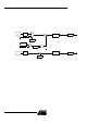
12.3 Timer 1 Timer 1 is identical to Timer 0 excepte d for Mo de 3 which is a hold-count m ode. Fol low-
ing comment s help to understand the differenc es:
• Time r 1 functions as either a Timer o r ev ent Count er in three modes of operation.
Figure 22 to Figure 24 show the logical confi gurat ion for m odes 0, 1, and 2. Timer
1’s mode 3 is a hold-count mode.
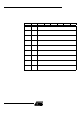
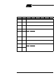
• Time r 1 is con trolled by the four high -o rder bits of TMO D registe r (see Figure 21)
and bits 2, 3, 6 and 7 of TCON register (see F igure 20). TMOD register selects the
method of Timer gating (GATE1), Timer or Cou nte r operat ion (C/T1#) and mode of
operation (M11 and M01). TCON register provides Timer 1 control fu nc tions :
overflow flag (TF 1), run control bit ( TR1), interrupt flag (IE1) and interrupt type
control bit (IT1).
• Timer 1 can serve as the Baud Rate Generat or f or the Serial Port. Mod e 2 is bes t
suited for this purpose.
• For normal Timer operation (GATE1= 0), set ting TR1 allows TL1 to be incremented
by the selected input . Setting GATE1 and TR1 allows external pin I NT1# to control
Timer ope ra tion.
• Time r 1 overflow (count rolls over from all 1s to all 0s) sets the TF1 flag generating
an interrupt reques t .
• When Timer 0 is in mode 3, it uses Timer 1’s overflow flag (TF1) and run control bit
(TR1). For this situation, use Timer 1 only for applications that do not require an
interrupt (such a s a Baud Rate Generator for the Serial Po rt) and switch Timer 1 in
and out of mode 3 to t urn it off and on.
• It is im portant to stop Timer/Counter be fore c hanging mode.
TR0
TCON.4
TF0
TCON.5
INT0#
0
1
GATE0
TMOD.3
Overflow
Timer 0
Interrupt
Request
C/T0#
TMOD.2
TL0
(8 bits)
TR1
TCON.6
TH0
(8 bits)
TF1
TCON.7
Overflow
Timer 1
Interrupt
Request
T0
FTx
CLOCK
÷ 6
FTx
CLOCK
÷ 6
see section “Clock”