
User Manual


48
T89C51AC2
Rev. B – 19-Dec-01
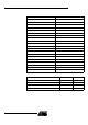
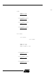
11.5 Registers Table 15. SCON Register
SCON (S:98h)
Serial Co ntrol Register
Rese t Value = 0000 0000b
Bit a ddres s able
76543210
FE/SM0 SM1 SM2 REN TB8 RB8 TI RI
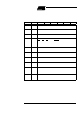
Bit
Number
Bit
Mnemonic Description
7FE
Framing Error bit (SMOD0=1)
Cleartoresettheerrorstate,notclearedbyavalidstopbit.
Set by hardware when an invalid stop bit is detected.
SM0
Serial port Mode bit 0 (SMOD0=0)
Refer to SM1 for serial port mode selection.
6SM1
Serial port Mode bit 1
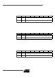
SM0
SM1 Mode Baud Rate
0 0 Shift Register F
XTAL
/12 (or F
XTAL
/6 in mode X2)
0 1 8-bit UART V ariable
1 0 9-bit UART F
XTAL
/64 or F
XTAL
/32
1 1 9-bit UART V ariable
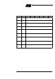
5SM2
Serial port Mode 2 bit / Multiprocessor Communication Enable bit
Clear to disable multiprocessor communication feature.
Set to enable multiprocessor communication feature in mode 2 and 3.
4REN
Reception Enable bit
Clear to disable serial reception.
Set to enable serial reception.
3TB8
Transmitter Bit 8 / Ninth bit to tran smit in modes 2 an d 3
Clear to transmit a logic 0 in the 9th bit.
Set to transmit a logic 1 in the 9th bit.
2RB8
Receiver Bit 8 / Nin th bit received in modes 2 and 3
Cleared by hardware i f 9th bit received is a logic 0.
Set by hardware if 9th bit received is a logic 1.
1TI
Transmi t Interrupt flag
Clear to acknowledge interrupt.
Set by hardware at the end of the 8th bit time in mode 0 or at the beginning of the
stop bit in the other modes.
0RI
Receive Interrupt flag
Clear to acknowledge interrupt.
Set by hardware at the end of t he 8th bit time in mode 0, see Figure 20. and
Figure 21. in the other modes.