
User Manual


46
T89C51AC2
Rev. B – 19-Dec-01
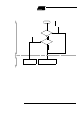
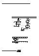
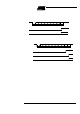
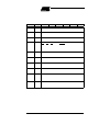
va lid s t op bits c annot clear the FE bit. When the FE feature is enabl ed, RI rises on the
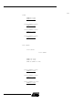
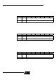
stop bit instead of the last data bit (S ee Figure 20. and Figure 21.).
Figure 20. UART Timing in Mod e 1
Figure 21. UART Timing in Modes 2 and 3
11.2 Automatic Address
Recognition
The au tomatic address recognition f eature is enabled when the multiprocessor commu-
nication feat ure is enabled (SM2 bit in SCON register is set).
Implemented in the hard w are, automatic address recognition enhances the multiproces -
sor communication feature by allowing the serial port to examine the address of each
incomi ng comm and fr ame. Onl y when the serial port rec ognizes its own address will the
rec eiver se t t he RI bit i n the SC ON regist er to generate an i nt errupt . Th is ens ures that
the CPU i s not interrup ted by co mmand frames addressed to other devices.
If nec es s ary, you can e nable the aut omatic address recogni t ion f eature in mode 1. In
this configuration, t he s top bit takes t he place of the ninth data bit. Bit RI is set only when
the rec eived command frame ad dres s m at c hes the de v ice’s a ddress and is terminated
by a valid s top bit.
To support automatic address recognit ion, a device is identified by a given address and
a broadcast address.
Note: The multiprocessor communication and aut omatic address recognition features cannot
be enabled in mode 0 (i.e. setting SM2 bit in SCON register in mode 0 has no effect).
11.3 Given Address Each dev ice ha s a n ind ividual add ress that is spe cified i n the S ADDR regi ster; the
SADEN regist er is a mask b y te that cont ains don’t-c are bit s (defined by zeros) to f orm
the device’s given addres s . The don’t-care b its provide the fle x ibi li ty to address one or
Data byte
RI
SMOD0=X
Stop
bit
Start
bit
RXD
D7D6D5D4D3D2D1D0
FE
SMOD0=1
RI
SMOD0=0
Data byte Ninth
bit
Stop
bit
Start
bit
RXD
D8D7D6D5D4D3D2D1D0
RI
SMOD0=1
FE
SMOD0=1