
User Manual


34
T89C51AC2
Rev. B – 19-Dec-01
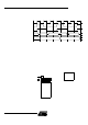
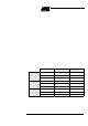
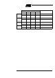
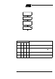
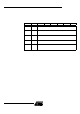
Table 10. Programming spaces
Note: The sequence 5xh and Axh must be executi ng wi thout instructions between them other-
wise the programming is abort ed.
Note: Interrupts that may occur during programming time must be disabled to avoid any spuri-
ous exit of t he programming mode.
9.3.3 Status of the flash
memory
The bit FBUSY in FCO N register is used to indicat e the status of programm ing.
FB USY is set when program mi ng i s in progress.
9.3.4 Sele cting FM1 The bit ENB OOT in AUXR1 register is used to map FM1 from F800h to FFFFh.
9.3.5 Loading the Column
Latches
Any number of data from 1 byte to 128 bytes can be loaded in the column latches. This
provides the capability to program the whole memory by byte, by pag e or by any number
of bytes in a page.
W hen programming is launc hed, an automatic erase of the locations loaded in the col-
umn latc hes is f irst perform ed, then program mi ng is effec tive ly done. Th us n o pa ge or
block erase is needed and only the loa ded da ta are programmed in the corres ponding
page.
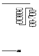
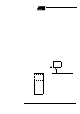
Th e f ol lowi ng p ro ced ur e is u se d to l oad the co lu mn la tche s a nd i s su m ma ri zed in
Figure 12:
• Disable interrupt and map the col umn latch space by setting FPS bit.
• Load the DPTR with the address t o load.
• Load Accumulator regist er with the data to load.
• Execute the MOVX @DPTR, A instruction.
• If needed loop the three last ins truct ions until the page is com pletely load ed.
• unmap the column latch an d E nable Interrupt
Write to FCON
OperationFPL3:0 FPS FMOD1 FMOD0
User
5 X 0 0 No action
AX0 0
Write the column latches in user
space
Extra Row
5 X 0 1 No action
AX0 1
Write the column latches in extra row
space
Hardware
Security
Byte
5 X 1 0 No action
A X 1 0 Write the fuse bits space
Reserved
5 X 1 1 No action
A X 1 1 No action