
User Manual

32
T89C51AC2
Rev. B – 19-Dec-01
9.2.1 FM 0 Memory
Architecture
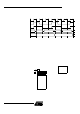
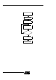
The flash mem ory is made up o f 4 blocks (see Figure 11):
3. The memory array (user space) 32 Kbytes
4. The Extra Row
5. The Hardwa re sec urity bits
6. The column latch reg isters
User Space This space is co mposed of a 32 Kby tes FLASH m emory organize d in 256 pages of 1 28
bytes. It conta ins the user’s application code.
Extra Row (XRow) This row is a part of FM0 and has a size of 128 bytes . The ex tra row m ay contain infor-
mation for boot loader usage.
Hardware security Byte The H ardware security B yte space is a part of FM0 and has a size of 1 byte.
The 4 MSB c an be read/written by softw are, the 4 LSB c an onl y be read by s oftware and
written by hardware in parallel mode.
Column latches The column l atches, also part of FM0, have a size of full page (128 bytes).
The column latches are the entrance buffers of the three previous m emory locations
(user array, XROW and Hardware security byte).
9.2.2 Cross Flash Memory
Access Description
The FM0 memory c an be program only from FM1. Programming FM0 from FM0 or from
external mem ory is imposs ible.
The FM1 memory can be program only by parallel programming.
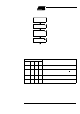
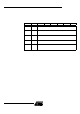
The Table 8 show all software flash ac ce ss allowed.
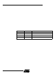
Table 8. C ross Flash M emory Access
Code executing from
Action
FM0
(user Flash)
FM1
(boot Flash)
FM0
(user Flash)
Read ok -
Load column latch ok -
Write - -
FM1
(boot flash)
Read ok ok
Load column latch ok -
Write ok -
External
memory
EA = 0
Read - -
Load column latch - -
Write - -