
User Manual


15
T89C51AC2
Rev. B – 19-Dec-01
6. Clock The T89C 51AC2 core needs only 6 clock periods per machine cycle. T his fea ture,
called”X2”, prov ides the foll owing advantages:
• Divides frequency crystals by 2 (che aper cr y s tals) while keeping the s ame CPU
power.
• Sa ves power consum ption while keeping the same CPU power (os cillator power
saving).
• Saves power consumption by dividing dy namic operating frequ enc y by 2 i n
operating and idle modes .
• Increases CPU power by 2 while keeping the same crystal frequency.
In order to keep the original C51 compatibility, a divider-by -2 is inserted between the
XT AL1 signal and the main clock input of the core (phase generat or). Thi s divider may
be disabled by the software.
An extra feature is available to start after Reset in the X 2 mode. This feature can be
enabled by a bit X2B in the Hardware Security Byte. This bit is described in the s ec tion
"In-System Program ming".
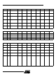
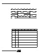
6.1 Description The X2 bit in the CKCON register (see Table 12) allows switching from 12 clock cycles
per instruction to 6 clock cycles and vice vers a. At res et , the standard speed is activated
(STD mode).
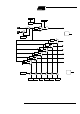
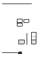
Setting t his bit activat es the X2 feat ure (X2 mode) f or the CPU Clock only (see Figure
5.).
The Timers 0, 1 and 2, Uart, P CA, or watchdog switch in X2 mode only if the corre-
sponding bit i s cleared in the C KCON register.
The clock for the whole circuit and peripheral is first divided by two before being used by
the C PU core and periphe rals. This allows any cyclic ratio to be acc epte d on the XTAL1
input. I n X2 mode, as this divider is bypassed, the signals on XTAL1 must have a cyclic
ratio between 40 to 60%. Figure 5. shows the cloc k generatio n b lock d iagram . T he X2
bit is v alidated on the XTAL1÷2 rising edge to avoid glitches w hen switching from the X2
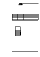
to the S TD mode. Figure 6 shows the mode switching wavef orm s .