
Manual

66
T48C862-R4
4551B–4BMCU–02/03
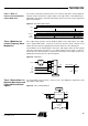
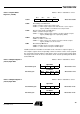
Timer 3 Capture Register The counter content can be read via the capture register. There are two ways to use the
capture register. In modes 1 and 4, it is possible to read the current counter value
directly out of the capture register. In the capture modes 2, 3, 5 and 12, a capture event
like an edge at the Timer 3 input or a signal from Timer 2 stores the current counter
value into the capture register. This counter value can be read from the capture register.
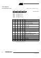
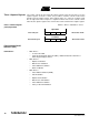
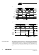
Timer 3 CaPture Register
(T3CP) Byte Read
Address: "B"hex - Subaddress: "4"hex
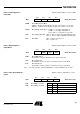
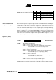
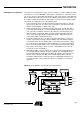
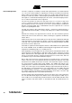
Synchronous Serial
Interface (SSI)
SSI Features: • With Timer 1:
– 2- and 3-wire NRZ
– 2-wire mode multi-chip link mode (MCL), additional internal 2-wire link for
multi-chip packaging solutions
• With Timer 2:
– Biphase modulation
– Manchester modulation
– Pulse-width demodulation
– Burst modulation
• With Timer 3:
– Pulse-width modulation (PWM)
– FSK modulation
– Biphase demodulation
– Manchester demodulation
– Pulse-width demodulation
– Pulse position Demodulation
High Nibble
First read cycle Bit 7 Bit 6 Bit 5 Bit 4 Reset value: xxxxb
Low Nibble
Second read cycle Bit 3 Bit 2 Bit 15 Bit 0 Reset value: xxxxb