
Manual

RF22
Version: 0.1 Date: 12/23/2008
Tel: +86-755-82973805 Fax: +86-755-82973550 E-mail: sales@hoperf.com http://www.hoperf.com
78
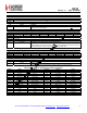
Register 52h. TX Ramp Control
Bit D7 D6 D5 D4 D3 D2 D1 D0
Name Reserved txmod[2:0] ldoramp[1:0] txramp[1:0]
Type R/W
R/W
R/W
R/W
Reset value = 00100000
Bit Name Function
7 Reserved Reserved
6:4 txmod[2:0] TX Modulation Delay.
The time delay between PA enable and the beginning of the TX modulation to allow for PA
ramp-up. It can be set from 0 µs to 28 µs in 4 µs steps. This also works during PA ramp down.
3:2 ldoramp[1:0] TX LDO Ramp Time.
The RF LDO is used to help ramp the PA to prevent VCO pulling and spectral splatter.
00: 5 µs
01: 10 µs
10: 15 µs
11: 20 µs
1:0 txramp[1:0] TX Ramp Time.
The PA is ramped up slowly to prevent VCO pulling and spectral splatter. This register sets the
time the PA is ramped up.
00: 5 µs
01: 10 µs
10: 15 µs
11: 20 µs
The total settling time (cold start) of the PLL after the calibration can be calculated as T
CS
= T
S
+ T
O
.
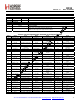
Register 53h. PLL Tune Time
Bit D7 D6 D5 D4 D3 D2 D1 D0
Name pllts[4:0] pllt0
Type R/W R/W
Reset value = 01010010
Bit Name Function
7:3 pllts[4:0] PLL Soft Settling Time (TS).
This register will set the settling time for the PLL from a previous locked frequency in Tune mode.
The value is configurable between 0 µs and 310 µs, in 10 µs intervals. The default plltime
corresponds to 100 µs. See formula above.
2:0 pllt0 PLL Settling Time (TO).
This register will set the time allowed for PLL settling after the calibrations are completed. The
value is configurable between 0 µs and 70 µs, in 10 µs steps. The default pllt0 corresponds to 20
µs. See formula above.
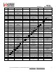
Register 54h. Reserved 1
Bit D7 D6 D5 D4 D3 D2 D1 D0
Name
Reserved
Reserved
Type R/W R/W
Reset value = 00001111
Bit Name Function
7:4 Reserved Reserved.
3:0 Reserved Reserved.