
Manual


RF22
Version: 0.1 Date: 12/23/2008
Tel: +86-755-82973805 Fax: +86-755-82973550 E-mail: sales@hoperf.com http://www.hoperf.com
43
obtain good antenna selection is 8 bytes. A special antenna diversity algorithm (antdiv[2:0] = 110 or 111) is included
that allows for shorter preamble for TDMA like systems where the arrival of the packet is synchronized to the receiver
enable. The recommended preamble length to obtain good antenna selection for synchronized mode is 4 byte.
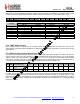
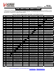
Add R/W Function/Description D7 D6 D5 D4 D3 D2 D1 D0 POR Def.
08 R/W Operating & Function Control 2 antdiv[2] antdiv[1] antdiv[0] rxmpk autotx enldm ffclrrx ffclrtx 00h
RX/TX State Non RX/TX State antdiv[2:0]
GPIO Ant1 GPIO Ant2 GPIO Ant1 GPIO Ant2
000 1 0 0 0
001 0 1 0 0
010 1 0 1 1
011 0 1 1 1
100 Antenna Diversity Algorithm 0 0
101 Antenna Diversity Algorithm 1 1
110 Antenna Diversity Algorithm in Beacon Mode 0 0
111 Antenna Diversity Algorithm in Beacon Mode 1 1
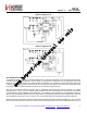
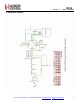
8.10. TX/RX Switch Control
When using the maximum output power of +20 dBm a TX/RX Switch (TRSW) may be required. The control for the
switch with the proper timing will be available on the GPIO pins. See application schematics for various options using a
TX/RX Switch.
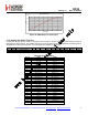
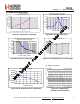
8.11. RSSI and Clear Channel Assessment
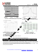
The RSSI (Received Signal Strength Indicator) signal is an estimate of the signal strength in the channel to which the
receiver is tuned. When sync word detection is enabled the RSSI value will be frozen after the sync word has been
detected. When sync word detection is disabled or a sync word is not detected, the RSSI value will be updated
continuously. The RSSI value can be read from an 8-bit register with 0.5 dB resolution per bit, for a total RSSI range of
127.5 dB. Figure 30 demonstrates the relationship between input power level and RSSI value.
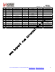
Add R/W Function/Description D7 D6 D5 D4 D3 D2 D1 D0
POR
Def.
26 R
Received Signal Strength
Indicator
rssi[7] rssi[6] rssi[5] rssi[4] rssi[3] rssi[2] rssi[1] rssi[0] —
27 R/W
RSSI Threshold for Clear
Channel Indicator
rssith[7] rssith[6] rssith[5] rssith[4] rssith[3] rssith[2] rssith[1] rssith[0] 00h
For Clear Channel Assessment a threshold is programmed into rssith[7:0] in "Register 27h. RSSI Threshold for Clear
Channel Indicator". After the RSSI is evaluated in the preamble, a decision is made if the signal strength on this
channel is above or below the threshold. If the signal strength is above the programmed threshold then a 1 will be
shown in the RSSI status bit in "Register 02h. Device Status", "Register 04h. Interrupt/Status 2", or configurable GPIO
(GPIOx[3:0] = 1110).