
Manual


RF22
Version: 0.1 Date: 12/23/2008
Tel: +86-755-82973805 Fax: +86-755-82973550 E-mail: sales@hoperf.com http://www.hoperf.com
34
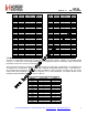
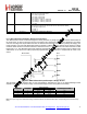
Table22. POR Parameters
Parameter Symbol Comment Min Typ Max Unit
Release Reset Voltage V
RR
0.85 1.3 1.75 V
Power-On VDD Slope S
VDD
tested V
DD
slope region 0.03 300 V/ms
Low VDD Limit V
LD
V
LD
<V
RR
is guaranteed 0.7 1 1.3 V
Software Reset Pulse T
SWRST
50 470 us
Threshold Voltage V
TSD
0.4 V
Reference Slope K 0.2 V/ms
VDD Glitch Reset Pulse T
P
Also occurs after SDN, and initial power on 5 15 40 ms
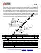
The reset will initialize all registers to their default values. The reset signal is also available for output and use by the
microcontroller by using the default setting for GPIO_0. The inverted reset signal is available by default on GPIO_1.
8.2. Microcontroller Clock
The crystal oscillator frequency is divided down internally and may be output to the microcontroller through GPIO2.This
feature is useful to lower BOM cost by using only one crystal in the system. The system clock frequency is selectable
from one of 8 options, as shown below. Except for the 32.768 kHz option, all other frequencies are derived by dividing
the Crystal Oscillator frequency. The 32.768 kHz clock signal is derived from an internal RC Oscillator or an external 32
kHz Crystal, depending on which is selected. The GPIO2 default is the microcontroller clock with a 1 MHz
microcontroller clock output.
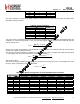
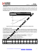
Add R/W Function/Description D7 D6 D5 D4 D3 D2 D1 D0 POR Def.
0A R/W Microcontroller Output Clock clkt[1] clkt[0] enlfc mclk[2] mclk[1] mclk[0] 0Bh
mclk[2:0] Modulation Source mclk[2:0] Modulation Source
000 30 MHz 100 3 MHz
001 15 MHz 101 2 MHz
010 10 MHz 110 1 MHz
011 4 MHz 111 32.768 kHz
If the microcontroller clock option is being used there may be the need of a System Clock for the microcontroller while
the RF22 is in SLEEP mode. Since the Crystal Oscillator is disabled in SLEEP mode in order to save current, the
low-power 32.768 kHz clock can be automatically switched to become the microcontroller clock. This feature is called
Enable Low Frequency Clock and is enabled by the enlfc bit. When enlfc = 1 and the chip is in SLEEP mode then the
32.768 kHz clock will be provided to the microcontroller as the System Clock, regardless of the setting of mclk[2:0]. For
example, if mclk[2:0] = 000, 30 MHz will be provided through the GPIO output pin to the microcontroller as the System
Clock in all IDLE, TX, or RX states. When the chip is commanded to SLEEP mode, the System Clock will become
32.768 kHz.
Another available feature for the microcontroller clock is the Clock Tail, clkt[1:0]. If the Enable Low Frequency Clock
feature is not enabled (enlfc = 0), then the System Clock to the microcontroller is disabled in SLEEP mode. However, it
may be useful to provide a few extra cycles for the microcontroller to complete its operation prior to the shutdown of the
System Clock signal. Setting the clkt[1:0] field will provide additional cycles of the System Clock before it shuts off.
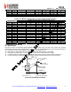
clkt[1:0] Modulation Source
00 0 cycles
01 128 cycles
10 256 cycles
11 512 cycles
If an interrupt is triggered, the microcontroller clock will remain enabled regardless of the selected mode. As soon as
the interrupt is read the state machine will then move to the selected mode. For instance, if the chip is commanded to
Sleep mode but an interrupt has occurred the 30 MHz XTAL will not disable until the interrupt has been cleared.