
User Manual
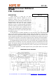

RF12B
Tel: +86-755-86096587 Fax: +86-755-86096602 E-mail: sales@hoperf.com http://www.hoperf.com
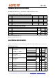
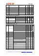
V
lb
Low battery detect threshold
Programmable in 0.1V
steps
2.2 3.7 V
V
lba
Low battery detection accuracy 0 5 %
V
il
Digital input low level voltage 0.3
*
V
dd
V
V
ih
Digital input high level voltage 0.7
*
V
dd
V
I
il
Digital input current V
il
= 0 V -1 1 µA
I
ih
Digital input current V
ih
= V
dd
, V
dd
= 3.8 V -1 1 µA
V
ol
Digital output low level I
ol
= 2 mA 0.4 V
V
oh
Digital output high level I
oh
= -2 mA V
dd
-0.4 V
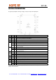
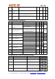
AC Characteristics (PLL parameters)
Symbol Parameter Conditions/Notes Min Typ Max Units
f
ref
PLL reference frequency (Note 1) 9 10 11 MHz
433 MHz band, 2.5 kHz resolution 430.24 439.75
868 MHz band, 5.0 kHz resolution 860.48 879.51
f
o
Receiver LO/Transmitter
carrier frequency
915 MHz band, 7.5 kHz resolution 900.72
929.27
MHz
t
lock
PLL lock time
Frequency error < 1kHz
ft 10 MH t
30 us
t
st, P
PLL startup time With a running crystal oscillator 200 300 us
AC Characteristics (Receiver)
Symbol Parameter Conditions/Notes Min Typ Max Units
mode 0 60 67 75
mode 1 120 134 150
mode 2 180 200 225
mode 3 240 270 300
mode 4 300 340 380
BW Receiver bandwidth
mode 5 360 400 450
kHz
BR
RX
FSK bit rate With internal digital filters 0.6 115.2 kbps
BRA
RX
FSK bit rate With analog filter 256 kbps
P
min
Receiver Sensitivity BER 10
-3
, BW=67 kHz, BR=1.2 kbps (Note 2) -109 -103 dBm
A
FC
range
AFC locking range
df
FSK
: FSK deviation in the received signal
0.8*df
FSK
IIP3
inh
Input IP3 In band interferers in high bands (868, 915 MHz) -21 dBm
Out of band interferers
IIP3
outh
Input IP3
l f-f
o
l > 4 MHz
-18 dBm
IIP3
inl
IIP3 (LNA –6 dB
gain)
In band interferers in low band (433 MHz) -15 dBm
Out of band interferers
IIP3
outl
IIP3 (LNA –6 dB
gain)
l f-f
o
l > 4 MHz
-12 dBm
P
max
Maximum input
power
LNA: high gain 0 dBm
C
in
RF input
capacitance
1 pF
RS
a
RSSI accuracy +/-5 dB
RS
r
RSSI range 46 dB