
User Manual

RF12B
Tel: +86-755-86096587 Fax: +86-755-86096602 E-mail: sales@hoperf.com http://www.hoperf.com
433 MHz
15 30 50 70 80 100 100
868 MHz
8 15 25 30 40 50 60
915 MHz
8 15 25 30 40 50 50
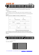
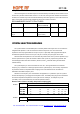
Bit Rate:
38.4 kbps
Deviation [+/- kHz]
30 45 60 75 90 105 120
315 MHz
don't use 7 30 50 75 100 100
433 MHz
don't use 5 20 30 50 75 75
868 MHz
don't use 3 10 20 25 30 40
915 MHz
don't use 3 10 15 25 30 40
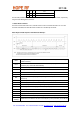
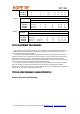
Bit Rate:
Deviation [+/- kHz]
115.2 kbps
105 120 135 150 165 180 195
315 MHz
don't use 4 30 50 70 100 100
433 MHz
don't use 3 20 30 50 70 80
868 MHz
don't use don't use 10 20 25 35 45
915 MHz
don't use don't use 10 15 25 30 40
RX-TX ALIGNMENT PROCEDURES
RX-TX frequency offset can be caused only by the differences in the actual reference frequency. To
minimize these errors it is suggested to use the same crystal type and the same PCB layout for the
crystal placement on the RX and TX PCBs.
To verify the possible RX-TX offset it is suggested to measure the CLK output of both chips with a
high level of accuracy. Do not measure the output at the XTL pin since the measurement process itself
will change the reference frequency. Since the carrier frequencies are derived from the reference
frequency, having identical reference frequencies and nominal frequency settings at the TX and RX side
there should be no offset if the CLK signals have identical frequencies.
It is possible to monitor the actual RX-TX offset using the AFC status report included in the status
byte of the receiver. By reading out the status byte from the receiver the actual measured offset
frequency will be reported. In order to get accurate values the AFC has to be disabled during the read by
clearing the "en" bit in the AFC Control Command (bit 0).
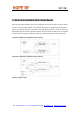
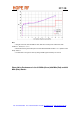
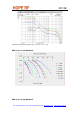
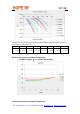
TYPICAL PERFORMANCE CHARACTERISTICS
Channel Selectivity and Blocking: