
User Manual

RF12B
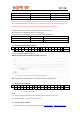
1 0 1 3.33
1 1 0 5
1 1 1 10
The low battery detector and the clock output can be enabled or disabled by bits eb and dc, respectively,
using the Power Management Command.
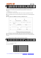
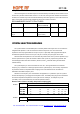
17. Status Read Command
The read command starts with a zero, whereas all other control commands start with a one. If a read
command is identified, the status bits will be clocked out on the SDO pin as follows:
Status Register Read Sequence with FIFO Read Example:
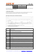
TX register is ready to receive the next byte (Can be cleared by Transmitter Registe
r
Write Command)
RGIT
The number of data bits in the RX FIFO has reached the pre-programmed limit (Can be
cleared by any of the FIFO read methods)
FFIT
POR Power-on reset (Cleared after Status Read Command)
RGUR TX register under run, register over write (Cleared after Status Read Command)
FFOV RX FIFO overflow (Cleared after Status Read Command)
WKUP Wake-up timer overflow (Cleared after Status Read Command)
Logic level on interrupt pin (pin 16) changed to low (Cleared after Status Rea
d
Command)
EXT
LBD Low battery detect, the power supply voltage is below the pre-programmed limit
FFEM FIFO is empty
ATS Antenna tuning circuit detected strong enough RF signal
RSSI The strength of the incoming signal is above the pre-programmed limit
DQD Data quality detector output
CRL Clock recovery locked
ATGL Toggling in each AFC cycle
OFFS(6) MSB of the measured frequency offset (sign of the offset value)
OFFS(3)
-OFFS(0)
Offset value to be added to the value of the frequency control parameter (Four LSB bits)
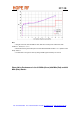
Note: In order to get accurate values the AFC has to be disabled during the read by clearing the "en" bit
Tel: +86-755-86096587 Fax: +86-755-86096602 E-mail: sales@hoperf.com http://www.hoperf.com