
User Manual

RF12B
Bit 4 (lpx): When this bit is set, low power mode of the crystal oscillator is selected.
lpx Crystal start-up time (typ) Power consumption (typ)
0 1 ms 620 uA
1 2 ms 460 uA
(Typ conditions: Top = 27 oC; Vdd = Voc = 2.7 V, Crystal ESR = 30 Ohm)
We have test that the default value(0) of bit lpx in PLL setting command will lead to
part of RF12B/RFM12B's oscillator fail. it should be set 1 in software manually. for
example, use 0xCC77 instead of 0xCC67 as PLL setting command.
Bit 3 (ddy): Switches on the delay in the phase detector when this bit is set.
Bit 2 (ddit): When set, disables the dithering in the PLL loop.
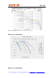
Bit 1-0 (bw1-bw0): PLL bandwidth can be set for optimal TX RF performance.
bw0 Max bit rate [kbps] Phase noise at 1MHz offset [dBc/Hz]
0 86.2 -107
1 256 -102
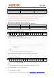
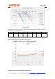
13. Transmitter Register Write Command
bit 15 14 13 12 11 10 9 8 7 6 5 4 3 2 1 0 POR
1 0 1 1 1 0 0 0 t7 t6 t5 t4 t3 t2 t1 t0 B8AAh
With this command, the controller can write 8 bits (t7 to t0) to the transmitter data register. Bit 7 (el) must
be set in Configuration Setting Command.
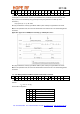
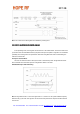
Multiple byte write with Transmit Register Write Command:
Note: Alternately the transmit register can be directly accessed by nFFSEL (pin6).
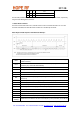
14. Wake-Up Timer Command
bit 15 14 13 12 11 10 9 8 7 6 5 4 3 2 1 0 POR
1 1 1 r4 r3 r2 r1 r0 m7 m6 m5 m4 m3 m2 m1 m0 E196h
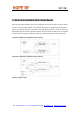
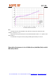
The wake-up time period can be calculated by (m7 to m0) and (r4 to r0):
Tel: +86-755-86096587 Fax: +86-755-86096602 E-mail: sales@hoperf.com http://www.hoperf.com
T
= M * 2
R
[ms]
wake-up
Note:
• For continual operation the et bit should be cleared and set at the end of every cycle.
• For future compatibility, use R in a range of 0 and 29.
15. Low Duty-Cycle Command