
User Manual


RF12B
Bit 1 (ff): FIFO fill will be enabled after synchron pattern reception. The FIFO fill stops when this bit is
cleared.
Bit 0 (dr): Disables the highly sensitive RESET mode. If this bit is cleared, a 500 mV glitch in the power
supply may cause a system reset.
Note: To restart the synchron pattern recognition, bit 1 should be cleared and set.
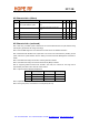
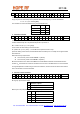
8. Synchron pattern Command
bit 15 14 13 12 11 10 9 8 7 6 5 4 3 2 1 0 POR
1 1 0 0 1 1 1 0 b7 b6 b5 b4 b3 b2 b1 b0 CED4h
The Byte0 used for synchron pattern detection can be reprogrammed by B <b7:b0>.
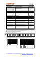
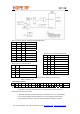
9.Receiver FIFO Read Command
bit 15 14 13 12 11 10 9 8 7 6 5 4 3 2 1 0 POR
1 0 1 1 0 0 0 0 0 0 0 0 0 0 0 0 B000h
With this command, the controller can read 8 bits from the receiver FIFO. Bit 6 (ef) must be set in
Configuration Setting Command.
Note: During FIFO access f
cannot be higher than f /4, where f
SCK ref ref
is the crystal oscillator frequency.
When the duty-cycle of the clock signal is not 50 % the shorter period of the clk pulse should be at least
2/f
second.
ref
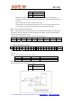
10.AFC Command
bit 15 14 13 12 11 10 9 8 7 6 5 4 3 2 1 0 POR
1 1 0 0 0 1 0 0 a1 a0 rl1 rl0 st fi oe en C4F7h
Bit 7-6 (a1 to a0): Automatic operation mode selector:
a1 a0
0 0 Auto mode off (Strobe is controlled by microcontroller)
0 1 Runs only once after each power-up
1 0 Keep the foffset only during receiving (VDI=high)
1 1 Keep the foffset value independently from the state of the VDI signal
Bit 5-4 (rl1 to rl0): Range limit. Limits the value of the frequency offset register to the next values:
rl1 rl0 Max deviation
Tel: +86-755-86096587 Fax: +86-755-86096602 E-mail: sales@hoperf.com http://www.hoperf.com
0 0 No restriction
0 1 +15 f
res
to -16 f
res
1 0 +7 f
res
to -8 f
res
1 1 +3 f
res
to -4 f
res
f :
res
315, 433 MHz bands: 2.5 kHz
868 MHz band: 5 kHz
915 MHz band: 7.5 kHz