
User Manual


RF12B
Tel: +86-755-86096587 Fax: +86-755-86096602 E-mail: sales@hoperf.com http://www.hoperf.com
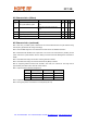
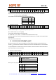
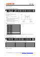
3. Frequency Setting Command
bit 15 14 13 12 11 10 9 8 7 6 5 4 3 2 1 0 POR
1 0 1 0 f11 f10f9f8f7f6f5f4f3f2f1 f0 A680h
The 12-bit parameter F (bits f11 to f0) should be in the range of 96 and 3903. When F value sent is out of
range, the previous value is kept. The synthesizer band center frequency f
0
can be calculated as:
f
0
= 10 * C1 * (C2 + F/4000) [MHz]
The constants C1 and C2 are determined by the selected band as:
Band [MHz] C1 C2
433 1 43
868 2 43
915 3 30
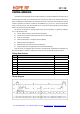
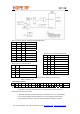
4. Data Rate Command
bit 15 14 13 12 11 10 9 8 7 6 5 4 3 2 1 0 POR
1 1 0 0 0 1 1 0 cs r6 r5 r4 r3 r2 r1 r0 C623h
The actual bit rate in transmit mode and the expected bit rate of the received data stream in receive
mode is determined by the 7-bit parameter R (bits r6 to r0) and bit cs.
BR = 10000 / 29 / (R+1) / (1+cs*7) [kbps]
In the receiver set R according to the next function:
R= (10000 / 29 / (1+cs*7) / BR) – 1, where BR is the expected bit rate in kbps.
Apart from setting custom values, the standard bit rates from 600 bps to 115.2 kbps can be approximated
with small error.
Data rate accuracy requirements:
z Clock recovery in slow mode: ΔBR/BR < 1/(29*N
bit
)
z Clock recovery in fast mode: ΔBR/BR < 3/(29*N
bit
)
BR is the bit rate set in the receiver and ΔBR is the bit rate difference between the transmitter and the
receiver. N
bit
is the maximum number of consecutive ones or zeros in the data stream. It is recommended
for long data packets to include enough 1/0 and 0/1 transitions, and to be careful to use the same division
ratio in the receiver and in the transmitter.
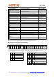
5. Receiver Control Command
Bit 15 14 13 12 11 10 9 8 7 6 5 4 3 2 1 0 POR
1 0 0 1 0 p16 d1 d0 i2 i1 i0 g1 g0 r2 r1 r0 9080h
Bit 10 (p16): pin16 function select
P16 Function of pin 16
0 Interrupt input
1 VDI output
Bits 9-8 (d1 to d0): VDI (valid data indicator) signal response time setting:
d1 d0 Response
0 0 Fast
0 1 Medium
1 0 Slow
1 1 Always on