
User Manual


RF12B
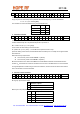
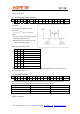
2. Power Management Command
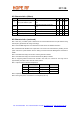
bit 15 14 13 12 11 10 9 8 7 6 5 4 3 2 1 0 POR
1 0 0 0 0 0 1 0 er ebb et es ex eb ew dc 8208h
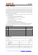
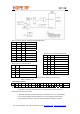
Bit Function of the control bit Related blocks
er Enables the whole receiver chain RF front end, baseband, synthesizer, oscillator
ebb The receiver baseband circuit can be separately switched on Baseband
et
Switches on the PLL, the power amplifier, and starts the
transmission (If TX register is enabled)
Power amplifier, synthesizer, oscillator
es Turns on the synthesizer Synthesizer
ex Turns on the crystal oscillator Crystal oscillator
eb Enables the low battery detector Low battery detector
ew Enables the wake-up timer Wake-up timer
dc Disables the clock output (pin 8) Clock output buffer
The ebb, es, and ex bits are provided to optimize the TX to RX or RX to TX turnaround time.
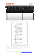
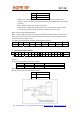
Logic connections between power control bits:
Note:
• If both et and er bits are set the chip goes to receive mode.
• FSK / nFFSEL input are equipped with internal pull-up resistor. To achieve minimum current
consumption do not pull this input to logic low in sleep mode.
Tel: +86-755-86096587 Fax: +86-755-86096602 E-mail: sales@hoperf.com http://www.hoperf.com