
User Manual

RF01
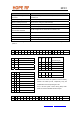
Control Commands
Control Word Related Parameters/Functions
Configuration Setting
Command
Frequency band, crystal oscillator load capacitance, baseband filter
bandwidth, etc.
Frequency Setting Command Set the frequency of the local oscillator
Receiver Setting Command Set VDI source, LNA gain, RSSI threshold,
Wake-up Timer Command Wake-up time period
Low Duty-Cycle Command Enable low duty cycle mode. Set duty-cycle.
Low Battery Detector and
Clock Divider Command
Set LBD voltage and microcontroller clock division ratio
AFC Control Command Set AFC parameters
Data Rate Command Bit rate
Data Filter Command Set data filter type, clock recovery parameters
Output and FIFO Command Set FIFO IT level, FIFO start control, FIFO enable and FIFO fill enable
Note: In the following tables the POR column shows the default values of the command registers after
power on.
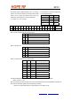
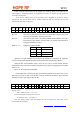
Configuration Setting Command
bit 15 14 13 12 11 10 9 8 7 6 5 4 3 2 1 0 POR
1 0 0 b1 b0 eb et ex x3 x2 x1 x0 i2 i1 i0 dc 893Ah
Crystal Load
Tel: +86-755-86096587 Fax: +86-755-86096602 E-mail: sales@hoperf.com http://www.hoperf.com
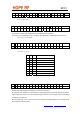
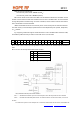
Frequency Setting Command
bit 15 14 13 12 11 10 9 8 7 6 5 4 3 2 1 0 POR
1 0 1 0 f11 f10 f9 f8 f7 f6 f5 f4 f3 f2 f1 f0 A680h
x3 x2 x1 x0
Capacitance [pF]
0 0 0 0 8.5
0 0 0 1 9.0
0 0 1 0 9.5
0 0 1 1 10.0
………….
1 1 1 0 15.5
1 1 1 1 16.0
b1 b0 Frequency Band [MHz]
0 0 315
0 1 433
1 0 868
1 1 915
i2 i1 i0 Baseband Bandwidth [kHz]
0 0 0 reserved
0 0 1 400
0 1 0 340
0 1 1 270
1 0 0 200
1 0 1 134
1 1 0 67
1 1 1 reserved
Bits eb and et control the operation of the low battery
detector and wake-up timer, respectively. They are
enabled when the corresponding bit is set.
If ex is set the crystal is active during sleep mode.
When dc bit is set it disables the clock output