
User Manual

RC220x
2005 Radiocrafts AS RC220x Data Sheet (rev. 1.0) Page 8 of 17
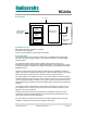
JTAG Interface
The module offers a JTAG interface for Flash and EEPROM programming, as well as for
debugging.
Programming through the JTAG interface requires control of the four JTAG specific pins:
TCK, TMS, TDI, and TDO. Control of the reset and clock pins is not normally required. To be
able to use the JTAG interface, the JTAGEN Fuse must be programmed. The device is
default shipped with the fuse programmed. For further information, please refer to the
respective MCU data sheet.
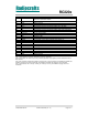
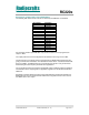
The table below show the JTAG pin mapping.
Signal RC2200 RC2202 RC2204
TDI 12 12 12
TDO 13 13 13
TMS 14 14 14
TCK 15 15 15
RESET 44 44 44
Supply and ground must also be connected during programming.
ISP Interface
The module offers an In-System Programming (ISP) interface for Flash and EEPROM
memory programming. The fastest way to do firmware downloading in manufacturing is
through the ISP interface rather then the JTAG interface.
The memory arrays can be programmed using the serial interface bus while RESET is pulled
to GND. The serial interface consists of pins SCK, PDI/MOSI (input) and PDO/MISO (output).
The RC2200 and RC2204 use the PDI and PDO pins (shared with UART0), while RC2202
use MOSI and MISO (shared with SPI interface), see table below.
After RESET is set low, the Programming Enable instruction needs to be executed first before
program/erase operations can be executed. More information is available in the respective
MCU data sheets.
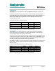
The table below show the pin mapping for ISP programming.
Signal RC2200 RC2202 RC2204
PDI 21 37 21
PDO 22 38 22
SCL 36 36 36
RESET 44 44 44
Supply and ground must also be connected during programming.