
User Manual

RC220x
2005 Radiocrafts AS RC220x Data Sheet (rev. 1.0) Page 4 of 17
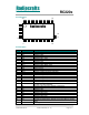
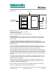
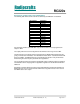
Pin Assignment
1
10
11 30
33
31
53 34
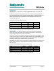
Pin Description
Pin no
Pin name Description and internal MCU connection
1 GND System ground
2 VCC Supply voltage input
3 PG0 Digital I/O, PG0
4 GND System ground
5 CTS1 Digital I/O, PD7 / CTS1
6 RTS1 Digital I/O, PD5 / RTS1
7 PG2 Digital I/O, PG2
8 TXD1 Digital I/O, PD3 / TXD1 / INT3
9 RXD1 Digital I/O, PD2 / RXD1 / INT2
10 GND System ground
11 GND System ground
12 ADC7 Digital or analogue I/O, PF7, JTAG TDI
13 ADC6 Digital or analogue I/O, PF6, JTAG TDO
14 ADC5 Digital or analogue I/O, PF5, JTAG TMS
15 ADC4 Digital or analogue I/O, PF4, JTAG TCK
16 ADC3 Digital or analogue I/O, PF3
17 ADC2 Digital or analogue I/O, PF2
18 ADC1 Digital or analogue I/O, PF1
19 ADC0 Digital or analogue I/O, PF0
20 AREF Analogue reference voltage pin for the internal A/D Converter.
Internally decoupled with 22nF.
21 PE0 Digital I/O, PE0, ISP PDI for RC2200 and RC2204
22 PE1 Digital I/O, PE1, ISP PDO for RC2200 and RC2204
23 PE2 Digital I/O, PE2
24 PE3 Digital I/O, PE3
25 PE4 Digital I/O, PE4 / INT4
26 PE5 Digital I/O, PE5 / INT5
27 PE6 Digital I/O, PE6 / INT6
28 PE7 Digital I/O, PE7 / INT7
29 1.8V Internally regulated voltage. Normally not connect. May be used for
AREF
30 GND System ground