
User Manual


MG260 Product Specification
This document is the sole and exclusive property of FLYFOT. Not to be distributed or divulged without prior written
agreement.
2.9.7 Auxiliary signals
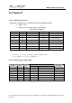
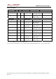
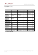
2.9.7.1 Analog to Digital Converter (AUXADC)
Parame
ter
Min
Max
Unit
R
e
solu
tion
10
bits
Sampling
rate
17
for
each
channel
or
68
on
sp
ecific channel
Ksp/s
Input signal range
0
2
V
Offset error
+/-
90
mV
Full scale error
+/-
25
mV
Integral linearity error
+/-
2
LSB
Differential linearity error
+/-
1
LSB
Input Impedance ( R )
100
(typ)
M
Ω
Input Impedance ( C )
4
(typ)
pF
Current consumption in
active state
600
µA
Current consumption in
power down state
1
µA
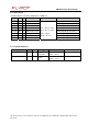
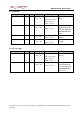
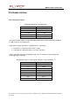
2.9.7.2 Digital to Analog Converter (AUXDAC)
Parame
ter
Min
Max
Unit
R
e
solu
tion
8
bits
Output voltage
0.16
2
V
Offset error
+/-
50
mV
Full scale error
+/-
50
mV
Integral linearity error
+/-
2
LSB
Differential linearity error
+/-
0.5
LSB
Output load ( R )
1
k
Ω
Output load ( C )
2
pF
Current consumption in
active state
560
µA
Current consumption in
power down state
1
µA
Setting time
5
µ
s