
User Manual


MG260 Product Specification
This document is the sole and exclusive property of FLYFOT. Not to be distributed or divulged without prior written
agreement.
2.9 Electrical characteristics
2.9.1 Power Supply
2.9.1.1 Introduction
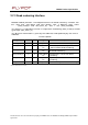
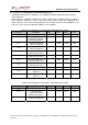
The table below sums up the power supply inputs / outputs available on the
MG260 module:
Power
sup
l
y
Pin
#
I/O
Description
VBATT
75,
77,
78,
79,
80
I Main power supply for both GPS and GSM
functions
GPS_
VAN
T
18
I
GPS
ante
nn
a
supply
VCC
60
O
2.8 V Power supply for external
digital devices
VCC_RTC
76
I/O
RTC
ba
ck-up
power
supply
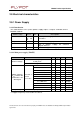
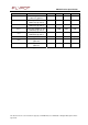
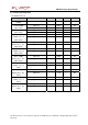
2.9.1.2 Main power supply (VBATT)
Parame
ter
Condition
Min
Typ
Max
Unit
Maximum
output
power
2.0
A
peak
3.4 3.8
4.2
V
VBATT
volt
age
Risi
n
g time
10
μ
s
f*
≤
100
k
H
z
10
mVpp
100
kHz
<
f
*<
400
kH
z
3
mVpp
f*=
400
kH
z
3
mVpp
f*=
6
00/
80
0/1
000
kH
z
0.5
mVpp
f*=
5
00/
70
0/9
00
k
H
z
1
mVpp
f*=
1100
kHz
1
mVpp
f*=
1200
kHz
1
mVpp
f*=
1300
kHz
2
mVpp
f*=
140
0/1
600
kHz
1
mVpp
f*=
150
0/1
700
kHz
3
mVpp
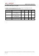
Ripple
voltage
(U
ripp
)
before
RF
parame
ter
s
are
damaged
At
T=25
°
C
And
V=3.8
V
f*=
1800
kHz
3
mVpp
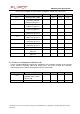
Drop
Voltage
Maximum
out
p
ut
po
wer
/
V=3.8
V
300
mV
f*=rippl
e frequency
measured
in
the
b
u
rst.