
User Manual


MG260 Product Specification
This document is the sole and exclusive property of FLYFOT. Not to be distributed or divulged without prior written
agreement.
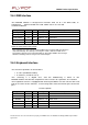
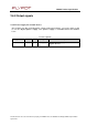
Signal
Pin
#
I/O
I/O type
Description
GPS_
EN
21
I/O
1
V8_
CMOS
Ac
tivation
of
the
GPS
fun
c
tion
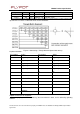
2.6.10.2 Digital to Analog Converter
MG260 provides a digital to analog converter.
This output voltage level varies according to a programmable value. It can be
used as a programmable voltage generator.
Pin
description
Signal
Pin
#
I/O
I/O
type
Description
AUXDAC
31
O
Analog
D/A
conver
ter
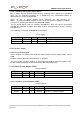
2.7 GPS interface
2.7.1 GPS activation
The GPS function can be activated/deactivated by hardware command
through the GPS_EN signal available on the system connector and acting as:
e
An input when GPS activation is hardware controlled,
Hardware
Ac
tivation
:
Hardware activation pin for GPS function is available on the system connector
(GPS_EN):
e
high logic level: enable the GPS section.
The voltage level of this signal has to be maintained between 2.4 V and
VBATT.
e
low logic level: disable the GPS section.
Pin description