
User Manual


MG260 Product Specification
This document is the sole and exclusive property of FLYFOT. Not to be distributed or divulged without prior written
agreement.
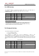
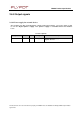
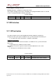
2.6.4 SIM interface
The MG260 module is designed to interface with 3V or 1.8V SIM cards, in
compliance with ETS 300 641 and 3GPP TS 51.011 V5.0.0
recommendations
Signal
Pin
#
I/O
I/O
type
Description
SIM
_CLK
23
O
2X
SIM
Clo
c
k
SIM
_
R
S
T
25
O
2X
SIM
Reset
SIM
_D
ATA
27
I/O
CMOS
/
3
X
SIM
Data
SIM
_
V
CC
29
O
-
SIM
P
o
we
r
Supply
SIM
_P
RES
70
I
CMOS
SIM
Card
Detect
N
o
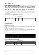
te
for
SIM_PRES
c
o
nne
ction
:
• The extraction of a card is reported if the SIMEN signal is pulled LOW; deactivation is
started immediately. The interrupt caused by this event is debounced with 14 ms.
Note that the interrupt is generated immediately. Any further SIMEN status changes
within the following 14 ms do not generate new interrupts.
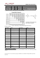
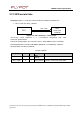
2.6.5 Keyboard interface
This
i
n
terf
ace
provid
es
8
connections:
•
4
rows
(
R
OW
0
to
R
O
W3
),
•
4
c
o
lumn
s
(COL
0
to
COL3
).
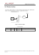
The scanning is a digital one, and the debouncing is done in the
MG260 module. No discrete components like resistors or capacitors are needed.
The keyboard scanner is equipped with internal pull-down resistors for the rows and
pull-up resistors for the columns. Current only flows from the column pins to the row
pins.
Pin
description
Signal
Pin
#
I/O
I/O
type
Description
RO
W0
33
I/O
CMOS
/
1X
Row
scan
RO
W1
35
I/O
CMOS
/
1X
Row
scan
RO
W2
37
I/O
CMOS
/
1X
Row
scan
RO
W3
39
I/O
CMOS
/
1X
Row
scan
COL0
43
I/O
CMOS
/
1X
Column
scan
COL1
45
I/O
CMOS
/
1X
Column
scan