
User Manual


MG260 Product Specification
This document is the sole and exclusive property of FLYFOT. Not to be distributed or divulged without prior written
agreement.
2.6.3 I
2
C interface
The I
2
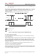
C BUS consists of a data line SDA and a clock line SCL. The data transport, clock
generation, address recognition and bus arbitration of this interface are all controlled directly by
hardware. The IIC-interface can operate according to two baud rate modes:
· Standard mode: The maximum baud rate is 100kbit/s. (standard IIC)
· Fast mode: The maximum baud rate is 400kbit/s. (Fast IIC)
Note: Devices with a 0 to 100kbit/s IIC-interface cannot be incorporated in the IIC-bus system, if the
400kbit/s fast mode is chosen. Unpredictable states of these devices would occur, since they
cannot follow the higher transfer rate.
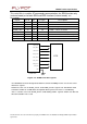
Pin
description
Signal
Pin
#
I/O
I/O
type
Description
SDA
28
I/O
CMOS/
3X
data
signal
SCL
30
O
3X
clo
c
k