
User Manual


MG260 Product Specification
This document is the sole and exclusive property of FLYFOT. Not to be distributed or divulged without prior written
agreement.
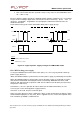
This serial link is used for AT commands communication, for GSM function only
(external mode) or for both GSM and GPS functions (internal mode).
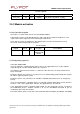
Pin
description
Signal
Pin
#
I/O
I/O
type
Description
GSM
_
T
X
D
1
59
I
CMOS
CT1
03
–
Tr
ansmit
Ser
i
al
Dat
a
GSM
_
R
X
D
1
52
O
3X
CT1
04
–
R
e
ceive
Seri
al
Dat
a
GSM
_
R
T
S
1
50
I
CMOS
CT1
05
–
R
e
quest
To
Send
GSM
_
CT
S
1
57
O
3X
CT1
06
–
Cl
ear
To
Se
n
d
GSM
_
D
S
R
1
56
O
3X
CT1
07
–
D
a
t
a
Set
Ready
GSM
_
DT
R
1
54
I
CMOS
CT1
08-
2
–
Dat
a
Terminal
Ready
GSM
_
DCD
1
71
O
CMOS/
2X
CT1
09
–
D
a
t
a
Carrier
Det
e
ct
GSM
_
R
I
1
74
O
CMOS/
2X
CT1
25
–
Ri
ng
I
n
dicat
o
r
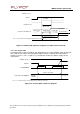
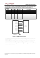
GSM_TXD1
GSM_RXD1
GSM_RTS1
GSM_CTS1
GSM_DSR1
GSM_DTR1
GSM_DCD1
GSM_RI1
GND
DTE
MG260
GSM
Serial
Link
Figure
13
:
GS
M
serial
link
signals
The
MG260
has
b
een
designed
to
allow
a
certai
n
flexibilit
y
in
the
use
of
the
serial
interface
signals.
However, the use of GSM_CTS1 and GSM_RTS1 signals for hardware flow
control in order to avoid data corruption during transmission is mandatory.
This is not the case for GSM_DTR1 and GSM_DSR1 signals which can be left
disconnected if not used.