
User Manual


MG260 Product Specification
This document is the sole and exclusive property of FLYFOT. Not to be distributed or divulged without prior written
agreement.
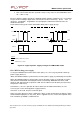
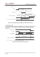
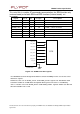
2.5.3.2 Reset sequence
To activate the « emergency » reset sequence, the RSTEXTN signal has to be set to low for
500s minimum.
As soon as the reset is complete, the AT interface answers « OK » to the application. For
this, the application has to send AT. If the application manages hardware flow control, the
AT command can be sent during the initialization phase. Another solution is to use the
AT+WIND command to get an unsolicited status from the module.
For further details, refer to AT commands documentation [4].
EX
T
E
R
N
AL
RS
T
M
i
n
:
500
μ
s
Typ
:
2
ms
A
T
a
n
sw
ers
“
O
K
”
Mod
u
le
R
E
ADY
ST
A
T
E
O
F
TH
E
MO
DU
LE
RESET
m
ode
I
BB+
RF
=
20
to
40
mA
Mod
u
le
O
N
I
BB+
RF
<
120
mA
with
ou
t
loc
u
pdate
Mod
u
le
R
E
ADY
S
I
M
an
d
n
e
t
w
or
k
depen
d
en
t
Figu
r
e
11
:
Re
se
t
se
q
u
e
n
ce
diag
r
a
m
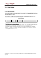
2.5.4 Activity status indication
The GSM and GPS activity status indication signals can be used to drive two LEDs
through an open-collector transistor according to the module activity status
.
Pin
description
Signal
Pin
#
I/O
I/O type
Description
FLAS
H
_
LE
D
72
I/O
CMOS/
2
x
GSM
Status
GPS_TIMEPLUSE
17
I/O
2V
8
_
CMO
S
GPS
Statu
s
FLASH
_
LED
GSM
status
OFF
Module
in
download
mode
or
m
o
dule
OFF
Permanent
Module switched ON, not registered on
the network
ON
Slow
flas
h
LED
ON
fo
r
200
ms,
OFF
for
2
s
Module switched ON, registered on the
network, no communication in progress.