
User Manual


MG260 Product Specification
This document is the sole and exclusive property of FLYFOT. Not to be distributed or divulged without prior written
agreement.
PO
W
E
R
SU
PP
L
Y
ON
KEY
T
on
/
o
ff
-
h
o
l
d
(1
s
m
i
n
)
IN
TE
R
N
A
L
R
S
T
ST
A
T
E
O
F
T
H
E
MO
DU
LE
Mo
du
l
e
OF
F
I
BB
+R
F
<
10
µ
A
T
rst
(2
40
m
s
t
y
p
)
RE
S
E
T
m
o
de
I
BB
+R
F
=2
0
to
40
m
A
Mo
du
l
e
ON
I
BB
+R
F
<1
20
m
A
(n
o
loc
.
upd
a
te
)
AT
an
swe
r
s
«
OK
»
Mo
du
l
e
RE
A
D
Y
SI
M
a
nd
Ne
t
w
or
k
d
e
pe
nde
n
t
I
BB+
RF
=
o
v
e
r
all
c
u
rr
e
n
t
co
n
s
um
p
t
i
o
n
(Ba
s
e
B
a
nd
+
RF
p
a
r
t
)
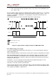
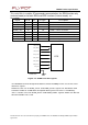
F
igure
9:
Power-ON
s
e
quence
diagra
m
(no
PIN
co
de
activ
a
ted)
2.5.2.2.2
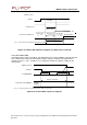
Power
OFF
To properly power OFF the module, the application must set the ONKEY signal to low and
then send the AT+CPOF command to de-register from the network and switch off the
module. Once the « OK » response is issued by the module, the power supply can be
switched off.
PO
WER
S
U
PP
L
Y
ON
KEY
AT
C
O
MM
A
N
D
AT
+
C
PO
F
OK
res
p
ons
e
ST
A
T
E
O
F
TH
E
MO
DU
LE
Mod
u
le
READY
Net
w
or
k
depen
d
en
t
Mod
u
le
O
FF
I
BB+
RF
<
100
µA
I
BB+R
F
=
o
v
e
r
all
c
u
rr
e
nt
c
o
ns
ump
t
i
o
n
(
B
as
e
B
a
nd
+
RF
par
t
)
Figure
10:
Power-OFF
sequence
diag
ram