
User Manual


MG260 Product Specification
This document is the sole and exclusive property of FLYFOT. Not to be distributed or divulged without prior written
agreement.
Common
Interface
GSM
Interface
GPS
Interface
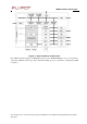
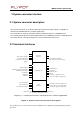
2 System connector interface
2.1 System connector description
The system connector is an 80-pin connector, with 0.5 mm pitch, which is available to
interface the MG260 with the customer application.
This connector is made by Panasonic with the following reference: AXK680347YG
The matting connector for customer application has the following reference: AXK580147YG
For further details, refer to paragraph 6.3, System Connector data sheet.
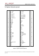
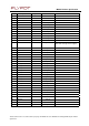
2.2 Functional interfaces
Main
Power
Supply(*)
Module
Activation(*)
Download
mode
control
Reset(*)
Activity
Status
Indication
Real
Time
Clock
Power
Supply
GSM
Serial
link(*)
GSM
Burst
Emission
Indication
GSM
External
Interrupt
GSM
GPIO
GSM
GPO
GSM
GPI
SIM
Interface(*)
Keyboard
Audio
interfaces
Buzzer
Analogue
to
Digital
Converter
3V
power
supply
for
peripherals
GPS
activation(*)
GPS
Serial
Link(*)
GPS
External
Interrupt
GPS
Active
antenna
management
GPS
SPI
Bus
for
Dead
Reckoning
1.8V
power
supply
for
peripherals
GROUND
Connection(*)
through
solder
joint
of
shielding
legs
(see
mechanical
drawing
for
details)
Legend:
(*)
=
minim
um
interfaces
requ
ire
d
for
the
customer
applicatio
n.
F
igure
6:
Sys
t
e
m
connector
functional
des
c
ript
ion