
Instruction Manual

MAX9937
Automotive Current-Sense Amplifier
with Reverse-Battery Protection
_______________________________________________________________________________________ 3
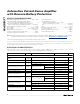
PARAMETER SYMBOL CONDITIONS MIN TYP MAX UNITS
Maximum Output Current I
OUT
R
RSN
= 500Ω, R
RSP
= 0, V
OUT
= 0 2 7.5 22 mA
V
SENSE
= 500mV, ΔI
OUT
≤ 1% -0.1
V
CC
+
0.1
Output-Voltage Compliance
(Note 6)
V
BAT
= 4V, V
SENSE
= 0.1V, ΔI
OUT
≤ 2% -0.1
V
RSP
-
0.15
V
RSP
-
0.8
V
Output-Voltage High V
OH
V
BAT
= 4V, V
SENSE
= +500mV,
V
OH
= V
BAT
- V
OUT
0.4 1.2 V
Output-Voltage Low V
OL
V
BAT
= 4V, V
SENSE
= -100mV 2 20 mV
AC CHARACTERISTICS
3dB Large-Signal Bandwidth BW V
SENSE
= 137.5mV
DC
+ 225mV
P-P
250 kHz
3dB Small-Signal Bandwidth 350 kHz
Settling Time to 1% t
S
5µs
Input-Voltage Noise e
n
f = 1kHz 28 nV/√Hz
Input Current Noise I
n
f = 1kHz 1 pA/√Hz
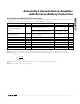
ELECTRICAL CHARACTERISTICS (continued)
(V
CC
= 5V, V
BAT
= V
RS+
= 12V, V
SENSE
= (V
RS+
- V
RS-
) = 0, R
RSP
= R
RSN
= 500Ω, R
OUT
= 10kΩ, T
A
= -40°C to +125°C. Typical
values are at T
A
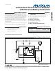
= +25°C, unless otherwise noted. See the
Typical Application Circuit
.) (Note 2)
Note 2: All devices are 100% production tested at T
A
= +25°C. Temperature limits are guaranteed by design.
Note 3: Gain and offset voltage are calculated based on two point measurements: V
SENSE1
= 5mV and V
SENSE2
= 200mV.
Note 4: Input bias current I
B+
and I
B-
refers to the internal op amp’s inputs (inverting and noninverting) so that I
B-
= I
RSN
and
I
B+
= I
RSP
- I
OUT
.
Note 5: The gain is set by the external resistors R
RSP
and R
OUT
. See the
Typical Application Circuit.
Note 6: V
RSP
= V
BAT
- V
SENSE
- V
OS
- (R
RSN
x I
B-
).
I
II
III
B
BB
BBB
=
+
=
+
+
-
-
-
2
Δ ||