
Owner's manual


MAX9877
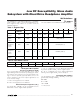
Table 6. Oscillator Modes
OSC
B1 B0
CLASS D OSCILLATOR MODE (kHz) CHARGE-PUMP OSCILLATOR MODE (kHz)
0 0 1176, spread spectrum 588, spread spectrum
0 1 1100, fixed frequency 550, fixed frequency
1 0 700, fixed frequency 350, fixed frequency
1 1 Reserved
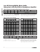
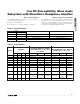
Table 7. Output Modes
OUTMODE
ΔIN_ = 0
(THE SINGLE-ENDED INPUT SIGNALS
ARE DEFINED AS IN_1 = LEFT AND
IN_2 = RIGHT)
ΔIN_ = 1
(THE DIFFERENTIAL INPUT SIGNAL IS
DEFINED AS IN_Δ = IN_2 - IN_1)
MODE
B3 B2 B1 B0 SPK LEFT HP RIGHT HP SPK LEFT HP RIGHT HP
0 0000 Reserved Reserved
1 0001INA1+INA2 — — INAΔ ——
2 0010 — INA1 INA2 — INAΔ INAΔ
3 0011INA1+INA2 INA1 INA2 INAΔ INAΔ INAΔ
4 0100INB1+INB2 — — INBΔ ——
5 0101 — INB1 INB2 — INBΔ INBΔ
6 0110INB1+INB2 INB1 INB2 INBΔ INBΔ INBΔ
7 0111
INA1+INA2
+INB1+INB2
— — INAΔ+INBΔ ——
8 1000 — INA1+INB1 INA2+INB2 —
INAΔ
+INBΔ
INAΔ +INBΔ
9 1001
INA1+INA2
+INB1+INB2
INA1+INB1 INA2+INB2 INAΔ+INBΔ
INAΔ
+INB_
INAΔ +INBΔ
10–15 Reserved Reserved
— = Amplifier Off
Low RF Susceptibility, Mono Audio
Subsystem with DirectDrive Headphone Amplifier
______________________________________________________________________________________ 23
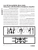
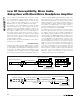
Bypass Mode (BYPASS)
1 = MAX9877 bypass switches are closed and the
Class D amplifier is disabled.
0 = Bypass mode disabled.
This mode does not control headphone operation.
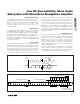
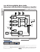
Output Configuration (OUTMODE)
The MAX9877 has a stereo DirectDrive headphone ampli-
fier and a mono Class D amplifier. Table 7 shows how
each of the output amplifiers can be configured and con-
nected to the input signals. For simplicity, not all possible
combinations of ΔINA and ΔINB are shown.