
Owner's manual


MAX9877
I
2
C Register Description
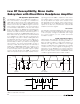
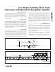
Zero-Crossing Detection (ZCD)
Zero-crossing detection limits distortion in the output
signal during volume transitions by delaying the transi-
tion until the mixer output crosses the internal bias volt-
age. A timeout period (typically 60ms) forces the
volume transition if the mixer output signal does not
cross the bias voltage.
1 = Zero-crossing detection is enabled.
0 = Zero-crossing detection is disabled.
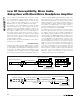
Differential Input Configuration (
Δ
IN_)
The inputs INA_ and INB_ can be configured for mono
differential or stereo single-ended operation.
1 = IN_ is configured as a mono differential input with
IN_2 as the positive and IN_1 as the negative input.
0 = IN_ is configured as a stereo single-ended input
with IN_2 as the right and IN_1 as the left input.
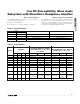
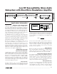
Preamplifier Gain (PGAIN_)
The preamplifier gain of INA_ and INB_ can be pro-
grammed by writing to PGAIN_.
00 = 0dB
01 = +9dB
10 = +20dB
11 = Reserved
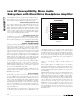
The MAX9877 is controlled through five I
2
C program-
mable registers. Table 1 shows the MAX9877’s com-
plete register map. Tables 2, 3, and 5 show the
individual registers.
I
2
C Address
The slave address of the MAX9877 is 1001101R/(W).
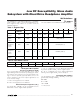
Table 1. Register Map
REGISTER
REGISTER
ADDRESS
POR STATE B7 B6 B5 B4 B3 B2 B1 B0
Input Mode
Control
0x00 0x40 0 ZCD ΔINA ΔINB PGAINA PGAINB
Speaker
Volume
Control
0x01 0x00 0 0 0 SVOL (Table 4)
Left
Headphone
Volume
Control
0x02 0x00 0 0 0 HPLVOL (Table 4)
Right
Headphone
Volume
Control
0x03 0x00 0 0 0 HPRVOL (Table 4)
Output Mode
Control
0x04 0x49 SHDN BYPASS OSC (Table 6) OUTMODE (Table 7)
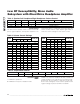
Table 2. Input Mode Control
REGISTER B7 B6 B5 B4 B3 B2 B1 B0
0x00 0 ZCD ΔINA ΔINB PGAINA PGAINB
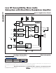
I
2
C Interface
Low RF Susceptibility, Mono Audio
Subsystem with DirectDrive Headphone Amplifier
______________________________________________________________________________________ 21