
Owner's manual


MAX9877
Low RF Susceptibility, Mono Audio
Subsystem with DirectDrive Headphone Amplifier
16 ______________________________________________________________________________________
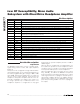
Pin Description
PIN NAME FUNCTION
A1 HPR Right Headphone Output
A2 HPL Left Headphone Output
A3 V
SS
Headphone Amplifier Negative Power Supply. Bypass with a 1µF capacitor to PGND.
A4 C1N Charge-Pump Flying Capacitor Negative Terminal. Connect a 1µF capacitor between C1P and C1N.
A5 C1P Charge-Pump Flying Capacitor Positive Terminal. Connect a 1µF capacitor between C1P and C1N.
B1 V
DD
Analog Supply. Connect to PV
DD
. Bypass with a 1µF capacitor to GND.
B2 BIAS
Common-Mode Bias. Bypass to GND with a 1µF capacitor. Pulse low to reset the part and place in
shutdown (see the Typical Application Circuit).
B3 SDA Serial-Data Input. Connect a pullup resistor from SDA to a 1.7V to 3.6V supply.
B4 RXIN+ Receiver Bypass Positive Input
B5 OUT+ Positive Speaker Output
C1 INB2 Input B2. Right input or positive input (see the Differential Input Configuration (ΔIN_) section).
C2 INB1 Input B1. Left input or negative input (see the Differential Input Configuration (ΔIN_) section).
C3 SCL Serial-Clock Input. Connect a pullup resistor from SCL to a 1.7V to 3.6V supply.
C4 PGND Power Ground
C5 PV
DD
Class D and Charge-Pump Power Supply. Bypass with a 1µF capacitor to PGND.
D1 INA2 Input A2. Right input or positive input (see the Differential Input Configuration (ΔIN_) section).
D2 INA1 Input A1. Left input or negative input (see the Differential Input Configuration (ΔIN_) section).
D3 GND Analog Ground
D4 RXIN- Receiver Bypass Negative Input
D5 OUT- Negative Speaker Output
Detailed Description
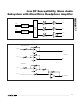
Signal Path
The MAX9877 signal path consists of flexible inputs,
signal mixing, volume control, and output amplifiers
(Figure 1).
The inputs can be configured for single-ended or differ-
ential signals (Figure 2). The internal preamplifiers fea-
ture three programmable gain settings of 0dB, +9dB,
and +20dB. Following preamplification, the input sig-
nals are mixed, volume adjusted, and routed to the
headphone and speaker amplifiers based on the out-
put mode configuration (see Table 7). The volume con-
trol stages provide up to 75dB attenuation. The
headphone amplifier is configured as a unity-gain
buffer while the speaker amplifier provides +12dB of
additional gain.
When an input is configured as mono differential it can
be routed to the speaker or to both headphones. When
an input is stereo, it is mixed to mono without attenuation
for the speaker and kept stereo for the headphones.
When the application does not require the use of both
INA_ and INB_, the SNR of the MAX9877 is improved
by deselecting the unused input through the I
2
C output
mode register and AC-coupling the unused inputs to
ground with a 330pF capacitor. The 330pF capacitor
and the input resistance to the MAX9877 form a high-
pass filter preventing audible noise from coupling into
the outputs.