
User guide

_______________________________________________________________________________________ 7
MAX98302
Stereo 2.4W Class D Amplifier
Pin Description
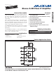
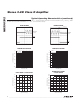
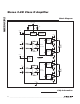
Pin Configuration
PIN NAME FUNCTION
1, 8, 14 PGND Ground
2 INL+ Noninverting Audio Left Input
3 INL- Inverting Audio Left Input
4 GAIN Gain Selection. See Table 1 for GAIN settings.
5 INR- Inverting Audio Right Input
6 INR+ Noninverting Audio Right Input
7
SHDN Active-Low Shutdown Input. Drive SHDN low to place the device in shutdown.
9 OUTR+ Positive Right Speaker Output
10 OUTR- Negative Right Speaker Output
11 PVDD
Power Supply. Bypass PVDD to PGND with a 0.1FF capacitor.
12 OUTL- Negative Left Speaker Output
13 OUTL+ Positive Left Speaker Outpout
— EP Exposed Pad. Connect EP to a solid ground plane.
MAX98302
TDFN
TOP VIEW
2
*CONNECT THE EP TO PGND TO ENHANCE THERMAL DISSIPATION.
4 5
13 11 10
OUTL+
PVDD
OUTR-
INL+
GAIN
INR-
1
EP*
14
PGNDPGND
3
12
OUTL-INL-
6
9
OUTR+INR+
7
8
PGNDSHDN
+