
Manual

Stereo Audio Codec
with FLEXSOUND Technology
MAX98088
83
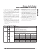
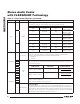
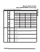
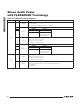
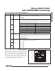
Table 11. Clock Control Registers (continued)
REGISTER BIT NAME DESCRIPTION
0x4F
7
DAI2_DAC_LP
DAI_ DAC Low Power Select.
These bits setup the clocks to be generated from fixed counters that bypass the PLL
for DAC low power mode.
6
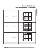
VALUE SETTING VALUE SETTING
0x0 PLL derived clock 0x8
PCLK = 2304 x
LRCLK
5 0x1
PCLK = 128 x
LRCLK
0x9 Reserved
4 0x2
PCLK = 192 x
LRCLK
0xA Reserved
3
DAI1_DAC_LP
0x3
PCLK = 256 x
LRCLK
0xB Reserved
0x4
PCLK = 384 x
LRCLK
0xC Reserved
2 0x5
PCLK = 768 x
LRCLK
0xD Reserved
1 0x6
PCLK = 1152 x
LRCLK
0xE Reserved
0 0x7
PCLK = 1536 x
LRCLK
0xF Reserved
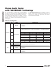
0x50
3 DAC2DITHEN
DIA2 DAC Input Dither Enable
DAC2DITHEN is recommended to be set when DAI2_DAC_LP = 0000.
0 = Disabled
1 = Enabled
2 DAC1DITHEN
DIA1 DAC Input Dither 1 Enable
DAC1DITHEN is recommended to be set when DAI1_DAC_LP = 0000.
0 = Disabled
1 = Enabled
1 CGM2_EN
DIA2 Clock Gen Module Enable
CGM1_EN has to be set along with CGM2_EN to enable the clock generation for the
DAI2 DAC playback path.
0 = Disabled
1 = Enabled
0 CGM1_EN
DIA1/Master Clock Gen Module Enable
CGM1_EN enables the master clock generation, and need to be set for DAC playback
or ADC record.
0 = Disabled
1 = Enabled