
Manual

Stereo Audio Codec
with FLEXSOUND Technology
MAX98088
81
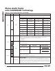
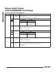
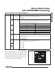
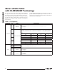
Table 11. Clock Control Registers
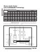
Clock Control
The digital signal paths in the IC require a master
clock (MCLK) between 10MHz and 60MHz to function.
Internally, the MAX98088/MAX98089 requires a clock
between 10MHz and 20MHz. A prescaler divides MCLK
by 1, 2, or 4 to create the internal clock (PCLK). PCLK is
used to clock all portions of the IC.
The MAX98088/MAX98089 includes two digital audio
signal paths, both capable of supporting any sample
rate from 8kHz to 96kHz. Each path is independently
configured to allow different sample rates. To accom-
modate a wide range of system architectures, three main
clocking modes are supported:
U PLL Mode: When operating in slave mode, enable
the PLL to lock onto any LRCLK input. This mode
requires the least configuration, but provides the
lowest performance. Use this mode to simplify initial
setup or when normal mode and exact integer mode
cannot be used.
U Normal Mode: This mode uses a 15-bit clock divider
to set the sample rate relative to PCLK. This allows
high flexibility in both the PCLK and LRCLK frequen-
cies and can be used in either master or slave mode.
U Exact Integer Mode (DAI1 only): In both master and
slave modes, common MCLK frequencies (12MHz,
13MHz, 16MHz, and 19.2MHz) can be programmed
to operate in exact integer mode for both 8kHz and
16kHz sample rates. In these modes, the MCLK and
LRCLK rates are selected by using the FREQ1 bits
instead of the NI, and PLL control bits.
U DAC Low-Power Mode: This mode bypasses the
PLL for reduce power consumptions and uses fixed
counters to generate the clocks. The DAI__DAC_LP
bits override the overclock settings.
REGISTER BIT NAME DESCRIPTION
0x10
5
PSCLK
MCLK Prescaler
Generates PCLK, which is used by all internal circuitry.
00 = PCLK disabled
01 = 10MHz P MCLK P 20MHz (PCLK = MCLK)
10 = 20MHz P MCLK P 40MHz (PCLK = MCLK/2)
11 = 40MHz P MCLK P 60MHz (PCLK = MCLK/4)
4
0x11/0x19
7
SR1/SR2
DAI1/DAI2 Sample Rate
Used by the ALC to correctly set the dual-band crossover frequency and the excursion
limiter to set the predefined corner frequencies.
6
VALUE
SAMPLE RATE
(kHz)
VALUE
SAMPLE RATE
(kHz)
0x0 Reserved 0x8 48
5
0x1 8 0x9 88.2
0x2 11.025 0xA 96
0x3 16 0xB Reserved
0x4 22.05 0xC Reserved
4
0x5 24 0xD Reserved
0x6 32 0xE Reserved
0x7 44.1 0xF Reserved