
Manual

MAX9670/MAX9671
Low-Power Audio/Video Switch with Audio
Volume Control for Dual SCART Connectors
28 ______________________________________________________________________________________
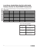
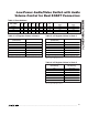
VIDEO ORIGIN FORMAT VOLTAGE RANGE COUPLING INPUT CIRCUIT CONFIGURATION
External CVBS Unknown AC Transparent sync-tip clamp
External RGB Unknown AC Transparent sync-tip clamp
External Y Unknown AC Transparent sync-tip clamp
External C Unknown AC Bias circuit
Internal CVBS 0 to 1V DC Transparent sync-tip clamp
Internal R, G, B 0 to 1V DC Transparent sync-tip clamp
Internal Y, C 0 to 1V DC Transparent sync-tip clamp
Internal Y, Pb, Pr 0 to 1V DC Transparent sync-tip clamp
Internal CVBS 2.3V to 3.3V AC Transparent sync-tip clamp
Internal R, G, B 2.3V to 3.3V AC Transparent sync-tip clamp
Internal Y 2.3V to 3.3V AC Transparent sync-tip clamp
Internal C 2.3V to 3.3V AC Bias circuit
Table 1. Recommended Coupling for Incoming Video Signals and Input Circuit
Configuration*
*
Use a 0.1µF capacitor to AC-couple a video signal into the MAX9670/MAX9671.
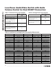
SLOW-SWITCHING
SIGNAL VOLTAGE
(V)
MODE
0 to 2
Display device uses an internal
source such as a built-in tuner to
provide a video signal.
4.5 to 7.0
Display device uses a video signal
from the SCART connector and sets
the display to 16:9 aspect ratio.
9.5 to 12.6
Display device uses a signal from the
SCART connector and sets the
display to 4:3 aspect ratio.
Table 2. Slow-Switching Modes