
Manual
MAX9595
Audio/Video Switch for Dual SCART Connector
_______________________________________________________________________________________ 5
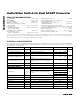
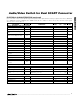
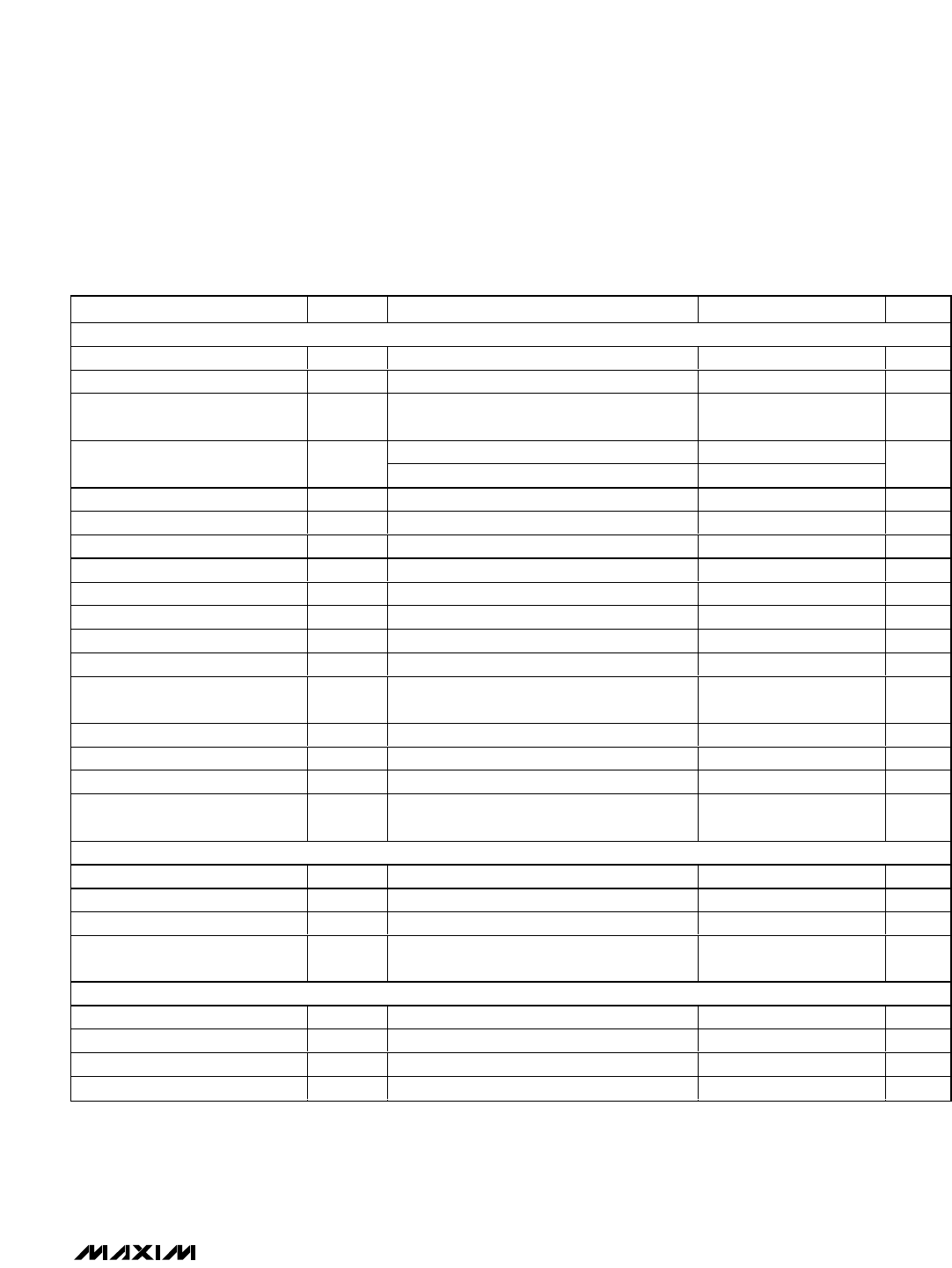
ELECTRICAL CHARACTERISTICS (continued)
(V
12
= 12V, V
VID
= V
AUD
= 5V; 0.1µF X5R capacitor in parallel with a 10µF aluminum electrolytic capacitor from V
AUD
to GNDAUD,
V
12
to GNDAUD, and V
VID
to GNDVID; SET = 100kΩ nominal, R
LOAD
= 150Ω, T
A
= 0°C to +70°C, unless otherwise noted. Typical
values are at T
A
= +25°C.) (Note 1)
PARAMETER
SYMBOL
CONDITIONS
MIN TYP MAX
UNIT
DIGITAL INTERFACE: SDA and SCL (Note 4)
Low-Level Input Voltage V
IL
0 0.8 V
High-Level Input Voltage V
IH
2.6 V
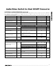
Hysteresis of Schmitt Trigger
Input
0.2 V
I
SINK
= 3mA 0.4
SDA Low-Level Output Voltage V
OL
I
SINK
= 6mA 0.6
V
Output Fall Time for SDA Line 400pF bus load
250
ns
Spike Suppression 50 ns
Input Current -10
+10
µA
Input Capacitance 5pF
SCL Clock Frequency 0
400
kHz
Hold Time
t
HD
,
STA
0.6 µs
Low Period of SCL Clock t
Low
1.3 µs
High Period of SCL Clock t
HIGH
0.6 µs
Setup Time for a Repeated Start
Condition
t
SU
,
STA
0.6 µs
Data Hold Time
t
HD
,
DAT
0 0.9 µs
Data Setup Time
t
SU
,
DAT
100
ns
Setup Time for Stop Condition
t
SU
,
STO
0.6 µs
Bus Free Time Between a Stop
and Start
t
BUF
1.3 µs
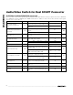
OTHER DIGITAL PINS (Note 4)
DEV_ADDR Low Level 0.8 V
DEV_ADDR High Level 2.6 V
INTERRUPT_OUT Low Voltage INTERRUPT_OUT sinking 1mA
0.15
0.4 V
INTERRUPT_OUT High Leakage
Current
V
INTERRUPT_OUT
= 5V 1 10 µA
SLOW SWITCHING SECTION (Note 4)
Input Low Level 02V
Input Medium Level 4.5 7.0 V
Input High Level 9.5 V
12
V
Input Current 50
100
µA