9-5472; Rev 1; 1/11 TION KIT EVALUA BLE IL AVA A Power-Management ICs for ICERA E400/E450 Platform Features The MAX8982A/MAX8982X are complete power-management ICs for the latest LTE/WCDMA/GSM/GPRS/ EDGE data card based on the new ICERA platform (E400/ E450). The MAX8982A operates from a 4.1V to 5.
MAX8982A/MAX8982X Power-Management ICs for ICERA E400/E450 Platform Table of Contents General Description . . . . . . . . . . . . . . . . . . . . . . . . . . . . . . . . . . . . . . . . . . . . . . . . . . . . . . . . . . . . . . . . . . . . . . . . . . . . . 1 Applications . . . . . . . . . . . . . . . . . . . . . . . . . . . . . . . . . . . . . . . . . . . . . . . . . . . . . . . . . . . . . . . . . . . . . . . . . . . . . . . . . . . 1 Features . . . . . . . . . . . . . . . . . . . . . . . . . . . . . .
Power-Management ICs for ICERA E400/E450 Platform Ramp-Up/Down Slope Control on BUCK1 . . . . . . . . . . . . . . . . . . . . . . . . . . . . . . . . . . . . . . . . . . . . . . . . . . . . . . . . 38 Setting the Output Voltage on BUCK2 . . . . . . . . . . . . . . . . . . . . . . . . . . . . . . . . . . . . . . . . . . . . . . . . . . . . . . . . . . . 38 Setting the Output Voltage on BUCK3 . . . . . . . . . . . . . . . . . . . . . . . . . . . . . . . . . . . . . . . . . . . . . . . . . . . . . . . . . . .
MAX8982A/MAX8982X Power-Management ICs for ICERA E400/E450 Platform Table of Contents (continued) List of Figures Figure 1. MAX8982A Typical Application Circuit and Functional Block Diagram . . . . . . . . . . . . . . . . . . . . . . . . . . . . . 31 Figure 2. MAX8982X Typical Application Circuit and Functional Block Diagram . . . . . . . . . . . . . . . . . . . . . . . . . . . . . 33 Figure 3. Power-On/Off State Diagram with IN3 Connected to BUCK2 Output and IN4 Connected to IN1_.
Power-Management ICs for ICERA E400/E450 Platform Table 14. LED1FT5 Register (LED1 (DR1) Flash Timer t4 Setting) . . . . . . . . . . . . . . . . . . . . . . . . . . . . . . . . . . . . . . . . 48 Table 15. LED1FT6 Register (LED1 (DR1) Flash Timer tP Setting) . . . . . . . . . . . . . . . . . . . . . . . . . . . . . . . . . . . . . . . . 48 Table 16. LED2FT1 Register (LED2 (DR2) Flash Timer On/Off and tON Adjust) . . . . . . . . . . . . . . . . . . . . . . . . . . . . . 48 Table 17.
MAX8982A/MAX8982X Power-Management ICs for ICERA E400/E450 Platform Table of Contents (continued) Table 51. On/Off Register (On/Off Control for BUCK3, BUCK4, and the Internal 32kHz Clock) . . . . . . . . . . . . . . . . . 64 Table 52. BUCK3 Register (Output Voltage Setting for BUCK3) . . . . . . . . . . . . . . . . . . . . . . . . . . . . . . . . . . . . . . . . . 64 Table 53. BUCK4 Register (Output Voltage Setting for BUCK4) . . . . . . . . . . . . . . . . . . . . . . . . . . . . . . . . . . . . . . . .
Power-Management ICs for ICERA E400/E450 Platform LX1 Continuous Current (Note 1)....................................1200mA LX2, LX3 Continuous Current (Note 1).............................600mA LX4 Continuous Current (Note 1)....................................1800mA Continuous Power Dissipation (TA = +70NC) 7x6 42-Bump WLP, 0.5mm Pitch, 3.75mm x 3.20mm (derate 27.8mW/NC above +70NC).................................2.22W Junction-to-Ambient Thermal Resistance (BJA) (Note 2).................................
MAX8982A/MAX8982X Power-Management ICs for ICERA E400/E450 Platform General ELECTRICAL CHARACTERISTICS (continued) (MAX8982A: VIN1A = VIN1B = +5.0V and COUT1,2,3+CIN_ = 1000FF, MAX8982X: VIN1A = VIN1B = +3.3V and COUT1,2,3+CIN_ = 20FF, CREFBP = 0.1FF, TA = -40NC to +85NC. Typical values are at TA = +25NC, unless otherwise noted.) (Note 3) PARAMETER CONDITIONS MIN TYP MAX UNITS OPERATING VOLTAGE IN1A, IN1B Operating Voltage Undervoltage Lockout MAX8982A 4.1 5.5 MAX8982X 2.9 5.
Power-Management ICs for ICERA E400/E450 Platform (MAX8982A: VIN1A = VIN1B = +5.0V and COUT1,2,3+CIN_ = 1000FF, MAX8982X: VIN1A = VIN1B = +3.3V and COUT1,2,3+CIN_ = 20FF, CREFBP = 0.1FF, TA = -40NC to +85NC. Typical values are at TA = +25NC, unless otherwise noted.) (Note 3) PARAMETER CONDITIONS MIN Maximum Pulse Width of Spikes that Must be Suppressed by the Input Filter of Both SDA and SCL Signals TYP MAX 50 Setup Time for STOP Condition (tSU_STO) UNITS ns 0.
MAX8982A/MAX8982X Power-Management ICs for ICERA E400/E450 Platform Buck2 Electrical Characteristics (MAX8982A: VIN1A = VIN1B = +5.0V and COUT1,2,3+CIN_ = 1000FF, MAX8982X: VIN1A = VIN1B = +3.3V and COUT1,2,3+CIN_ = 20FF, CREFBP = 0.1FF, COUT = 2.2FF, L = 1FH, TA = -40NC to +85NC, unless otherwise noted. Typical values are at TA = +25NC.) (Note 3) PARAMETER CONDITIONS MIN TYP MAX Supply Current (Note 4) No load, no switching Output Voltage ILOAD = 100mA Output Current VBUCK2 = 1.
Power-Management ICs for ICERA E400/E450 Platform (MAX8982A only, VIN1A = VIN1B = +5.0V, COUT1,2,3+CIN_ = 1000FF, CREFBP = 0.1FF, COUT = 2.2FF, L = 2.2FH, TA = -40NC to +85NC, unless otherwise noted. Typical values are at TA = +25NC.) (Note 3) PARAMETER Current Limit On-Resistance CONDITIONS MIN TYP pFET switch 700 1100 1500 nFET rectifier 500 750 1200 pFET switch, ILX3 = -150mA 0.65 nFET rectifier, ILX3 = 150mA 0.
MAX8982A/MAX8982X Power-Management ICs for ICERA E400/E450 Platform OUT1 (LDO1) Electrical Characteristics (MAX8982A: VDDA = +3.2V and CVDD_ = 10FF, MAX8982X: VDDA = +3.3V and CVDD_ = 20FF, CREFBP = 0.1FF, COUT1 = 4.7FF, TA = -40NC to +85NC, unless otherwise noted. Typical values are at TA = +25NC.) (Note 3) PARAMETER Default Output Voltage CONDITION ILOAD = 50mA Maximum Output Current MIN TYP MAX UNITS 2.619 2.70 2.
Power-Management ICs for ICERA E400/E450 Platform (MAX8982A: VDDA = +3.2V and CVDD_ = 10FF, MAX8982X: VDDA = +3.3V and CVDD_ = 20FF, CREFBP = 0.1FF, COUT2 = 1FF, TA = -40NC to +85NC, unless otherwise noted. Typical values are at TA = +25NC.) (Note 3) PARAMETER CONDITION MIN TYP 1.50 1.80 2.70 1.
MAX8982A/MAX8982X Power-Management ICs for ICERA E400/E450 Platform OUT4 (LDO4) Electrical Characteristics (MAX8982A/MAX8982X: VIN3 = VBUCK2 = 1.8V, CIN3 = 2.2FF, CREFBP = 0.1FF, COUT4 = 2.2FF, TA = -40NC to +85NC, unless otherwise noted. Typical values are at TA = +25NC.) (Note 3) PARAMETER Default Output Voltage CONDITION ILOAD = 10mA Maximum Output Current MIN TYP MAX 0.873 0.9 0.
Power-Management ICs for ICERA E400/E450 Platform (MAX8982A: VDDB = +3.2V and CVDD_ = 10FF, MAX8982X: VDDB = +3.3V and CVDD_ = 20FF, CREFBP = 0.1FF, COUT6 = 1FF, TA = -40NC to +85NC, unless otherwise noted. Typical values are at TA = +25NC.) (Note 3) PARAMETER Default Output Voltage CONDITION ILOAD = 50mA Maximum Output Current MIN TYP MAX 2.619 2.70 2.
MAX8982A/MAX8982X Power-Management ICs for ICERA E400/E450 Platform OUT8 (LDO8) Electrical Characteristics (MAX8982A only, VIN4 = VIN1_ = +5.0V, CIN4 = 1.0FF, CREFBP = 0.1FF, COUT8 = 1FF, TA = -40NC to +85NC, unless otherwise noted. Typical values are at TA = +25NC.) (Note 3) PARAMETER CONDITION Input Operating Range Guaranteed by output voltage accuracy Overvoltage Lockout (Shutdown LDO8 Output) VIN4 rising, VIN1_ = VIN4 MIN 3.0 5.
Power-Management ICs for ICERA E400/E450 Platform (MAX8982A/MAX8982X: VIN3 = VBUCK2 = 1.8V, CIN3 = 2.2FF, CREFBP = 0.1FF, COUT9 = 2.2FF, TA = -40NC to +85NC, unless otherwise noted. Typical values are at TA = +25NC.
MAX8982A/MAX8982X Power-Management ICs for ICERA E400/E450 Platform Flash Timer Electrical Characteristics (MAX8982A: VIN1A = VIN1B = +5V and VDD_ = +3.2V, MAX8982X: VIN1A = VIN1B = +3.3V and VDD_ = +3.3V, CREFBP = 0.1FF, TA = -40NC to +85NC, unless otherwise noted. Typical values are at TA = +25NC.
Power-Management ICs for ICERA E400/E450 Platform (MAX8982A: VIN1A = VIN1B = +5V and VDD_ = +3.2V, MAX8982X: VIN1A = VIN1B = +3.3V and VDD_ = +3.3V, CREFBP = 0.1FF, TA = -40NC to +85NC, unless otherwise noted. Typical values are at TA = +25NC.) (Note 4, Figure 11) PARAMETER CONDITIONS MIN TYP 25 Programmable On-Time, tON MAX 25 (0000) 50 (0001) 75 . . 400 (1111) 4-bit programmable in 25ms steps, same for each flash timer UNITS 400 ms N32kHz Electrical Characteristics (MAX8982A: VDD_ = +3.
Typical Operating Characteristics (continued) (MAX8982A: VIN1A = VIN1B = 5V, MAX8982X: VIN1A = VIN1B = VDDA = VDDB = VIN4 = 3.3V, CREFBP = 0.1µF, TA = -40°C to +85°C, Circuits of Figures 2 and 3, unless otherwise noted. Typical values are at TA = +25°C. Limits are 100% production tested at TA = +25NC, unless otherwise noted. Limits over the temperature range are guaranteed by design.) NO LOAD SUPPLY CURRENT vs. INPUT VOLTAGE (MAX8982X) BUCK1 LOAD REGULATION L = 2.
Power-Management ICs for ICERA E400/E450 Platform (MAX8982A: VIN1A = VIN1B = 5V, MAX8982X: VIN1A = VIN1B = VDDA = VDDB = VIN4 = 3.3V, CREFBP = 0.1µF, TA = -40°C to +85°C, Circuits of Figures 2 and 3, unless otherwise noted. Typical values are at TA = +25°C. Limits are 100% production tested at TA = +25NC, unless otherwise noted. Limits over the temperature range are guaranteed by design.) BUCK1 RAMP-UP TRANSITION BUCK1 RAMP-DOWN TRANSITION MAX8982A toc10 MAX8982A toc11 1.2V VBUCK1 1.2V VBUCK1 0.
Typical Operating Characteristics (continued) (MAX8982A: VIN1A = VIN1B = 5V, MAX8982X: VIN1A = VIN1B = VDDA = VDDB = VIN4 = 3.3V, CREFBP = 0.1µF, TA = -40°C to +85°C, Circuits of Figures 2 and 3, unless otherwise noted. Typical values are at TA = +25°C. Limits are 100% production tested at TA = +25NC, unless otherwise noted. Limits over the temperature range are guaranteed by design.) MAX8982A toc16 100 VOUT = 3.2V COUT = 10µF AC-COUPLED 100mV/div 90 EFFICIENCY (%) VBUCK3 85 VIN = 5V 80 VIN = 5.
Power-Management ICs for ICERA E400/E450 Platform (MAX8982A: VIN1A = VIN1B = 5V, MAX8982X: VIN1A = VIN1B = VDDA = VDDB = VIN4 = 3.3V, CREFBP = 0.1µF, TA = -40°C to +85°C, Circuits of Figures 2 and 3, unless otherwise noted. Typical values are at TA = +25°C. Limits are 100% production tested at TA = +25NC, unless otherwise noted. Limits over the temperature range are guaranteed by design.) BUCK4 SWITCHING FREQUENCY vs. TEMPERATURE (MAX8982A ONLY) 2.00 1.95 2.702 2.701 2.700 1.90 2.699 1.85 2.698 1.
Typical Operating Characteristics (continued) (MAX8982A: VIN1A = VIN1B = 5V, MAX8982X: VIN1A = VIN1B = VDDA = VDDB = VIN4 = 3.3V, CREFBP = 0.1µF, TA = -40°C to +85°C, Circuits of Figures 2 and 3, unless otherwise noted. Typical values are at TA = +25°C. Limits are 100% production tested at TA = +25NC, unless otherwise noted. Limits over the temperature range are guaranteed by design.) LDO8 LOAD REGULATION (MAX8982A ONLY) LDO7 LOAD REGULATION 3.015 3.010 OUTPUT VOLTAGE (V) 3.015 MAX8982A toc30 3.020 3.
Power-Management ICs for ICERA E400/E450 Platform TOP VIEW (BUMP ON BOTTOM) MAX8982A 1 2 3 4 5 6 7 A N32 kHz OUT9 GND REF BP OUT6 OUT3 OUT2 B OUT4 DR1 DR2 OUT8 VSIM VDDB VDDA C IN3 DR3 RESET OUT5 SCL IRQ OUT1 D LX2 BUCK2 DVS1 SDA PWR_ REQ BUCK3 LX3 E PGND2 BUCK1 EN IN1B LX4 BUCK4 PGND3 F PGND1 LX1 IN4 IN1A LX4 PGND4 PGND4 WLP 25 MAX8982A/MAX8982X Pin Configurations
Power-Management ICs for ICERA E400/E450 Platform MAX8982A/MAX8982X Pin Configurations (continued) TOP VIEW (BUMP ON BOTTOM) MAX8982X 1 2 3 4 5 6 7 A N32 kHz OUT9 GND REF BP OUT6 OUT3 OUT2 B OUT4 DR1 DR2 DNC VSIM VDDB VDDA C IN3 DR3 RESET OUT5 SCL IRQ OUT1 D LX2 BUCK2 DVS1 SDA PWR_ REQ DNC DNC E PGND2 BUCK1 EN IN1B DNC DNC PGND3 F PGND1 LX1 IN4 IN1A DNC PGND4 PGND4 WLP 26
Power-Management ICs for ICERA E400/E450 Platform PIN NAME MAX8982A MAX8982X FUNCTION GROUND A3 GND GND F1 PGND1 PGND1 Power Ground for BUCK1 Analog Ground E1 PGND2 PGND2 Power Ground for BUCK2 E7 PGND3 PGND3 Power Ground for BUCK3 F6, F7 PGND4 PGND4 Power Ground for BUCK4 INPUT SUPPLY Input Supply to the IC. The operating voltage range for the MAX8982A is 4.1V to 5.5V. Connect three 330FF tantalum capacitors as close as possible to IN1A and IN1B. Connect IN1A to IN1B.
MAX8982A/MAX8982X Power-Management ICs for ICERA E400/E450 Platform Pin Description (continued) NAME MAX8982A MAX8982X LDO REGULATORS PIN FUNCTION C7 OUT1 OUT1 LDO1 Output. Bypass OUT1 with a 4.7FF ceramic capacitor. OUT1 supplies loads up to 300mA. The default output voltage is 2.7V. A7 OUT2 OUT2 LDO2 Output. Bypass OUT2 with a 1FF ceramic capacitor. OUT2 supplies loads up to 150mA. The default output voltage is 1.8V. A6 OUT3 OUT3 LDO3 Output. Bypass OUT3 with a 1FF ceramic capacitor.
Power-Management ICs for ICERA E400/E450 Platform NAME MAX8982A MAX8982X LOGIC OUTPUTS PIN C6 IRQ C3 RESET REFERENCE OUTPUT A4 FUNCTION IRQ RESET Active-Low, Open-Drain Interrupt Output. Internal pullup resistor, 200kI, to BUCK2. Active-Low, Open-Drain Reset Output. There is an internal 14kI pullup resistor to BUCK2. REFBP REFBP Reference Bypass. Connect the reference bypass capacitor from REFBP to GND. See Table 3. High impedance in off condition. VREFBP is 0.8V (typ).
MAX8982A/MAX8982X Power-Management ICs for ICERA E400/E450 Platform Table 1. Summary of Power Supplies (continued) PARAMETER BUCK1 BUCK2 BUCK3* BUCK4* OUT1 OUT2 OUT3 Default ON at Initial Startup PWR_ REQ ON ON OFF PWR_ PWR_ REQ REQ ON ON/OFF Control After Power-Up I2C or PWR_ REQ I2C or PWR_ REQ I2C or PWR_ REQ I2C or PWR_ REQ I 2C I2C or or PWR_ PWR_ REQ REQ I2C or PWR_ REQ OFF ON OFF OFF Default Active Discharge Resistor *BUCK3, BUCK4, and OUT8 are for the MAX8982A only.
Power-Management ICs for ICERA E400/E450 Platform IN1_ ON/OFF SEQUENCE STEP-DOWN CONVERTER 4 (1.8A) OVP 330µF * 3 SHUTDOWN SIGNAL LX4 0.9V 3.4V (DEFAULT) 3.0V TO 3.75V IN 50mV STEPS 2.2µF GSM PA/ UMTS PA PGND4 PGND4 GND BB 2.2µH N 5.75V REFBP LX4 P 3.8V IN1B 0.1µF IN1A UVLO IN1A 5V DD+ G MAX8982A/MAX8982X USB INPUT BUCK4 IN3 OUT9 IN1A 2.2µF P LDO9 (50mA) STEP-DOWN DC-DC 1 CONVERTER (1.2A) IN1B N UVLO (3.8V) LX1 REF (0.8V) 2.2µH 0.9V (DEFAULT) 0.6V TO 1.
MAX8982A/MAX8982X Power-Management ICs for ICERA E400/E450 Platform Table 2. External Component List for Figure 1 LOCATION IN1A, IN1B EXTERNAL COMPONENTS NOTES IN3 3 x 330FF tantalum capacitors 2.2FF Buck stability and GSM PA supply IN4 1.0FF Input for LDO8 OUT1 4.7FF LDO compensation and load transient response OUT2 1.0FF LDO compensation OUT3 1.0FF LDO compensation OUT4 2.2FF LDO compensation OUT5 1.0FF LDO compensation OUT6 1.0FF LDO compensation VSIM (OUT7) 1.
Power-Management ICs for ICERA E400/E450 Platform MAX8982A/MAX8982X IN1A VDDB P VDDA 3.3V INPUT OVP IN1A 22µF STEP-DOWN DC-DC 1 CONVERTER (1.2A) SHUTDOWN SIGNAL 5.75V IN1B UVLO IN4 LX1 2.2µH 0.9V (DEFAULT) 0.6V TO 1.2V IN 25mV STEPS CORE 2.2µF N PGND1 ON/OFF SEQUENCE 2.7V BUCK1 DVS1 REFBP DCDC 1 SEL IN1A 0.1µF GND 0.9V VCC_USB P IN3 OUT9 2.2µF STEP-DOWN DC-DC 2 CONVERTER (DEFAULT ON, 600mA) IN1B LDO9 (50mA) UVLO (2.7V) N REF (0.8V) 1µH LX2 1.8V VCC_IO 2.
MAX8982A/MAX8982X Power-Management ICs for ICERA E400/E450 Platform Table 3. External Component List for Figure 2 LOCATION EXTERNAL COMPONENTS IN1A, IN1B NOTES Buck stability 22FF 2.2FF IN3 Input for LDO4 and LDO9 IN4 Connect to IN1A and IN1B OUT1 4.7FF LDO compensation and load transient response OUT2 1.0FF LDO compensation OUT3 1.0FF LDO compensation OUT4 2.2FF LDO compensation OUT5 1.0FF LDO compensation OUT6 1.0FF LDO compensation VSIM (OUT7) 1.
Power-Management ICs for ICERA E400/E450 Platform SHUTDOWN ALL REGULATORS DISABLED I2C HIGH IMPEDANCE REF DISABLED 32kHz DISABLED enable this discharge resistor, set the appropriate bit in the BUCK1-4ADIS, LDO1-8ADIS, or LDO9ADIS register. The active discharge resistor values are specified in the General Electrical Characteristics table. VIN1_ < 3.5V (MAX8982A) OR VIN1_ < 2.4V (MAX8982X) OR VIN1_ > 5.75V OR EN = LOW FROM ANY STATE VIN1_ > 3.8V (TYP) (MAX8982A) VIN1_ > 2.
MAX8982A/MAX8982X Power-Management ICs for ICERA E400/E450 Platform EN AND IN1_ UVLO RISING ON SEQUENCING RESTARTS WHEN INPUT IS ABOVE UVLO RISING THRESHOLD UVLO FALLING ~16ms BUCK 3 (3.2V) 125µs BUCK 2 FOR IO (1.8V) 225µs 32kHz OUTPUT CONTINUOUS OUT 3 FOR ANALOG (2.8V) 375µs OUT 8 125µs FOR USB (3.0V) OUT 9 125µs FOR BB (0.9V) 625µs RESET OTHER ONREGULATORS 31µs 31µs TO 62µs IRQ OPERATING STATE OFF POWER-ON SEQUENCE ON OFF POWER-ON SEQUENCE Figure 4.
Power-Management ICs for ICERA E400/E450 Platform MAX8982A/MAX8982X PWR_REQ GROUP A : OUT 2,* ~10µs BUCK 2, BUCK 3** (BUILT-IN TIME DELAY TO ENABLE REGULATORS) OUTPUT DECAY DEPENDS ON THE LOAD GROUP B : LDO1,* 100µs OUT 3, BUCK 4** GROUP C : OUT6,* 200µs OUT5, OUT7, OUT8** GROUP D : BUCK 1*, OUT4,* 375µs OUT9 *THESE REGULATORS DEFAULT TO PWR_REQ CONTROL. THE OTHERS MUST BE PROGRAMED TO PWR_REQ CONTROL BY I2C. **BUCK3, BUCK4, AND OUT8 ARE FOR THE MAX8982A ONLY. Figure 5.
MAX8982A/MAX8982X Power-Management ICs for ICERA E400/E450 Platform Ramp-Up/Down Slope Control on BUCK1 Reference Bypass (REFBP) BUCK1 uses a controlled ramp rate when it is enabled and when changing between output voltage settings. Four programmable slew rates are available for BUCK1. The default value is 12.5mV/Fs (Table 4). The same slew rate is applied for ramp-up/down. The reference bypass is for low noise filtering only and must not be loaded. Bypass REFBP with a 0.1FF ceramic capacitor.
Power-Management ICs for ICERA E400/E450 Platform EN = HIGH AND IN1_ VALID EN = LOW OR IN1_ INVALID I2C ENABLED THE VALUES IN THE BUCK1DVS1 AND BUCK1DVS2 REGISTERS ARE RESET TO THEIR DEFAULTS WHEN PWR_REQ GOES LOW PWR _REQ = LOW Figure 9. POR State Diagram Current Regulators (DR1, DR2, DR3) The ICs have three current regulators that can handle up to 24mA. The sink current for each current regulator is set from 3mA to 24mA in 3mA increments through I2C.
MAX8982A/MAX8982X Power-Management ICs for ICERA E400/E450 Platform SDA SCL DATA LINE STABLE DATA VALID CHANGE OF DATA ALLOWED Figure 12. I2C Bit Transfer RESET SIGNAL to B/B Chipset The ICs include one dedicated reset output called RESET. This is the reset signal for the core and RTB (real-time block) in baseband. RESET goes high after the ICs’ power-up sequence is complete. RESET is pulled low when the ICs are shut down (due to input supply out of range or EN goes low).
Power-Management ICs for ICERA E400/E450 Platform Acknowledge The number of data bytes between the START and STOP conditions for the transmitter and receiver are unlimited. Each 8-bit byte is followed by an acknowledge bit. The acknowledge bit is a high-level signal put on SDA by the transmitter during which time the master generates an extra acknowledge-related clock pulse. A slave receiver that is addressed must generate an acknowledge after each byte it receives.
MAX8982A/MAX8982X Power-Management ICs for ICERA E400/E450 Platform SDA tLOW tBUF tSU_STA tSU_DAT tHD_STA tSU_STO tHD_DAT tHIGH SCL tHD_STA tF tR START CONDITION REPEATED START CONDITION STOP CONDITION START CONDITION Figure 16.
Power-Management ICs for ICERA E400/E450 Platform The master sends the 8-bit register pointer of the first register to write. 4) The master sends an 8-bit register pointer of the first register in the block. 5) The slave acknowledges the register pointer. 5) The slave acknowledges the register pointer. 6) The master sends a data byte. 6) The master sends a repeated START condition. 7) The slave acknowledges the data byte. 7) 8) The slave updates with the new data.
MAX8982A/MAX8982X Power-Management ICs for ICERA E400/E450 Platform Table 5.
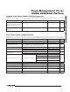
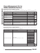
Power-Management ICs for ICERA E400/E450 Platform ADDRESS POR R/W (HEX) (HEX) 5A BIT 7 (MSB) NAME 01 R/W LDO8 BIT 6 BIT 5 BIT 4 BIT 3 BIT 2 BIT 1 Reserved Reserved Reserved Reserved Reserved Reserved Reserved Reserved Reserved BIT 0 (LSB) LDO8[1:0] 5B 06 R/W LDO8V 5C 01 R/W LDO9 L8[4:0] 5D 00 R/W LDO9V Reserved Reserved Reserved 6B 00 R/W LED_EN Reserved Reserved Reserved Reserved Reserved 70 03 R/W ON/OFF Reserved Reserved Reserved 72 06 R/W BUCK3 Reserved Reserve
MAX8982A/MAX8982X Power-Management ICs for ICERA E400/E450 Platform Table 8. IRQ Register ADDRESS (HEX) POR (HEX) R/W BIT 7 BIT 6 BIT 5 BIT 4 BIT 3 BIT 2 BIT 1 BIT 0 13 00 R/W Reserved Reserved Reserved Reserved Reserved Reserved UVLOF HIGH TMP NAME POR DESCRIPTION HIGH TMP 0 0: No high temperature event detected. 1: Temperature sensor detects +125NC. UVLOF 0 0: No UVLO event detected. 1: UVLO falling is detected.
Power-Management ICs for ICERA E400/E450 Platform ADDRESS (HEX) POR (HEX) R/W BIT 7 19 00 R/W Reserved NAME BIT 6 BIT 5 BIT 4 BIT 3 BIT 2 BIT 1 BIT 0 t1 TIME (ms) LD1T1[6:0] POR DESCRIPTION BIT LD1T1[0:6] 0000000 MAX8982A/MAX8982X Table 11. LED1FT2 Register (LED1 (DR1) Flash Timer t1 Setting) 6 5 4 3 2 1 0 0 0 0 0 0 0 0 0 0 0 0 0 0 0 1 25 . . . . . . . . . . . . . . . .
MAX8982A/MAX8982X Power-Management ICs for ICERA E400/E450 Platform Table 14. LED1FT5 Register (LED1 (DR1) Flash Timer t4 Setting) ADDRESS (HEX) POR (HEX) R/W BIT 7 1C 00 R/W Reserved NAME BIT 6 BIT 5 BIT 4 BIT 3 BIT 2 BIT 1 BIT 0 1 0 t4 TIME (ms) LD1T4[6:0] POR DESCRIPTION BIT 6 LD1T4[6:0] 0000000 5 4 3 2 0 0 0 0 0 0 0 0 0 0 0 0 0 0 1 25 0 0 0 0 0 1 0 50 . . . . . . . . . . . . . . . .
Power-Management ICs for ICERA E400/E450 Platform ADDRESS (HEX) POR (HEX) R/W BIT 7 21 00 R/W Reserved NAME BIT 6 BIT 5 BIT 4 BIT 3 BIT 2 BIT 1 BIT 0 t1 TIME (ms) LD2T1[6:0] POR DESCRIPTION BIT LD2T1[6:0] 0000000 6 5 4 3 2 1 0 0 0 0 0 0 0 0 0 0 . . 1 0 . . 1 0 . . 1 0 . . 1 0 . . 1 0 . . 1 1 . . 1 25 . . 3175 BIT 2 BIT 1 BIT 0 t2 TIME (ms) From 0ms to 3175ms in 25ms increments. Table 18.
MAX8982A/MAX8982X Power-Management ICs for ICERA E400/E450 Platform Table 20. LED2FT5 Register (LED2 (DR2) Flash Timer t4 Setting) ADDRESS (HEX) POR (HEX) R/W BIT 7 24 00 R/W Reserved NAME BIT 6 BIT 5 BIT 3 BIT 4 BIT 2 BIT 1 1 0 0 1 . . 1 0 0 1 0 . . 1 BIT 2 BIT 1 BIT 0 LD2T4[6:0] POR DESCRIPTION BIT LD2T4[6:0] 0000000 BIT 0 6 5 4 3 0 0 0 0 0 0 0 0 0 0 0 0 . . . . . . . . 1 1 1 1 2 0 0 0 . . 1 t4 TIME (ms) 0 25 50 . .
Power-Management ICs for ICERA E400/E450 Platform ADDRESS (HEX) POR (HEX) R/W BIT 7 29 00 R/W Reserved NAME BIT 6 BIT 5 BIT 4 BIT 3 BIT 2 BIT 1 BIT 0 t1 TIME (ms) LD3T1[6:0] POR DESCRIPTION BIT LD3T1[6:0] 0000000 6 5 4 3 2 1 0 0 0 0 0 0 0 0 0 0 0 0 0 0 0 1 25 0 0 0 0 0 1 0 50 . . . . . . . . . . . . . . . . 1 1 1 1 1 1 1 3175 BIT 2 BIT 1 BIT 0 t2 TIME (ms) From 0ms to 3175ms in 25ms increments. Table 24.
MAX8982A/MAX8982X Power-Management ICs for ICERA E400/E450 Platform Table 26. LED3FT5 Register (LED3 (DR3) Flash Timer t4 Setting) ADDRESS (HEX) POR (HEX) R/W BIT 7 2C 00 R/W Reserved NAME BIT 6 BIT 5 BIT 4 BIT 3 BIT 2 BIT 1 BIT 0 LD3T4[6:0] POR DESCRIPTION BIT LD3T4[6:0] 0000000 6 5 4 3 2 1 0 t4 TIME (ms) 0 0 0 0 0 0 0 0 0 0 0 0 0 0 1 25 0 0 0 0 0 1 0 50 . . . . . . . . . . . . . . . .
Power-Management ICs for ICERA E400/E450 Platform ADDRESS (HEX) POR (HEX) R/W BIT 7 BIT 6 BIT 5 3F 0C R/W Reserved Reserved Reserved BITS 7:5 BIT 4 BIT 3 BIT 2 BIT 1 MAX8982A/MAX8982X Table 29. BUCK1DVS1 Register (Output Voltage Setting for BUCK1 (DVS1 = Low)) BIT 0 SD1[4:0] Reserved, write 000 to these bits. DESCRIPTION BIT 4 BIT 3 BIT 2 BIT 1 BIT 0 VPROG (V) 0 0 0 0 0 0.600 0 0 0 0 1 0.625 0 0 0 1 0 0.650 0 0 0 1 1 0.675 0 0 1 0 0 0.
MAX8982A/MAX8982X Power-Management ICs for ICERA E400/E450 Platform Table 30. BUCK1DVS2 Register (Output Voltage Setting for BUCK1 (DVS1 = High)) ADDRESS (HEX) POR (HEX) 40 0C BITS 7:5 R/W BIT 7 BIT 6 BIT 5 BIT 4 R/W Reserved Reserved Reserved BIT 3 BIT 2 BIT 1 SD1[4:0] Reserved, write 000 to these bits. DESCRIPTION BIT 4 BIT 2 BIT 1 BIT 0 VPROG (V) 0 0 0 0 0 0.600 0 0 0 0 1 0.625 0 0 0 1 0 0.650 0 0 0 1 1 0.675 0 0 1 0 0 0.700 0 0 1 0 1 0.
Power-Management ICs for ICERA E400/E450 Platform ADDRESS (HEX) POR (HEX) R/W BIT 7 BIT 6 BIT 5 BIT 4 BIT 3 BIT 2 45 45 R/W Reserved Reserved Reserved Reserved Reserved Reserved BITS 7:2 BIT 1 MAX8982A/MAX8982X Table 31. BUCK2 Register (On/Off Control for BUCK2) BIT 0 BUCK2[1:0] Reserved, write 010001 to these bits. BIT 1 BIT 0 0 0 DESCRIPTION BUCK2 off (in I2C on mode). 0 1 BUCK2 on (in I2C on mode). 1 0 BUCK2 on (in PWR_REQ on mode) (Group A).
MAX8982A/MAX8982X Power-Management ICs for ICERA E400/E450 Platform Table 34. LDO2 Register (ON/OFF Control for LDO2) ADDRESS (HEX) POR (HEX) R/W BIT 7 BIT 6 BIT 5 BIT 4 BIT 3 BIT 2 4E 03 R/W Reserved Reserved Reserved Reserved Reserved Reserved BITS 7:2 BIT 1 BIT 0 LDO2[1:0] Reserved, write 000000 to these bits. BIT 1 BIT 0 0 0 LDO2 off (in I2C on mode). DESCRIPTION 0 1 LDO2 on (in I2C on mode). 1 0 LDO2 on (in PWR_REQ on mode) (Group A).
Power-Management ICs for ICERA E400/E450 Platform ADDRESS (HEX) POR (HEX) R/W BIT 7 BIT 6 BIT 5 51 07 R/W Reserved Reserved Reserved BITS 7:5 BIT 4 BIT 3 BIT 2 BIT 1 MAX8982A/MAX8982X Table 37. LDO3V Register (Output Voltage Setting for OUT3) BIT 0 L3[4:0] Reserved, write 000 to these bits. DESCRIPTION BIT 4 BIT 3 BIT 2 BIT 1 BIT 0 VPROG (V) 0 0 0 0 0 2.65 0 0 0 0 1 2.65 0 0 0 1 0 2.65 0 0 0 1 1 2.65 0 0 1 0 0 2.70 0 0 1 0 1 2.
MAX8982A/MAX8982X Power-Management ICs for ICERA E400/E450 Platform Table 39. LDO4V Register (Output Voltage Setting for OUT4) ADDRESS (HEX) POR (HEX) R/W 53 00 R/W BITS 7:5 BIT 7 BIT 6 BIT 5 BIT 4 Reserved Reserved Reserved BIT 3 BIT 2 BIT 1 BIT 0 L4[4:0] Reserved, write 000 to these bits. DESCRIPTION BIT 4 BIT 3 BIT 2 BIT 1 BIT 0 VPROG (V) 0 0 0 0 0 0.90 0 0 0 0 1 1.00 0 0 0 1 0 1.20 0 0 0 1 1 1.10 X X 1 X X 0.80 X 1 X X X 0.
Power-Management ICs for ICERA E400/E450 Platform ADDRESS (HEX) POR (HEX) R/W BIT 7 BIT 6 BIT 5 55 07 R/W Reserved Reserved Reserved BITS 7:5 BIT 4 BIT 3 BIT 2 BIT 1 MAX8982A/MAX8982X Table 41. LDO5V Register (Output Voltage Setting for OUT5) BIT 0 L5[4:0] Reserved, write 000 to these bits. DESCRIPTION BIT 4 BIT 3 BIT 2 BIT 1 BIT 0 VPROG (V) 0 0 0 0 0 3.20 0 0 0 0 1 3.20 0 0 0 1 0 3.20 0 0 0 1 1 3.20 0 0 1 0 0 3.20 0 0 1 0 1 2.
MAX8982A/MAX8982X Power-Management ICs for ICERA E400/E450 Platform Table 43. LDO6V Register (Output Voltage Setting for OUT6) ADDRESS (HEX) POR (HEX) R/W BIT 7 BIT 6 BIT 5 57 07 R/W Reserved Reserved Reserved BITS 7:5 BIT 4 BIT 3 BIT 2 BIT 1 BIT 0 L6[4:0] Reserved, write 000 to these bits. DESCRIPTION BIT 4 BIT 3 BIT 2 BIT 1 BIT 0 VPROG (V) 0 0 0 0 0 2.65 0 0 0 0 1 2.65 0 0 0 1 0 2.65 0 0 0 1 1 2.65 0 0 1 0 0 2.65 0 0 1 0 1 2.
Power-Management ICs for ICERA E400/E450 Platform ADDRESS (HEX) POR (HEX) R/W BIT 7 BIT 6 BIT 5 59 0B R/W Reserved Reserved Reserved BITS 7:5 BIT 4 BIT 3 BIT 2 BIT 1 MAX8982A/MAX8982X Table 45. VSIMV Register (Output Voltage Setting for VSIM) BIT 0 L7[4:0] Reserved, write 000 to these bits. DESCRIPTION BIT 4 BIT 3 BIT 2 BIT 1 BIT 0 VPROG (V) 0 0 0 0 0 1.80 0 0 0 0 1 1.80 0 0 0 1 0 1.80 0 0 0 1 1 1.80 0 0 1 0 0 1.80 0 0 1 0 1 1.
MAX8982A/MAX8982X Power-Management ICs for ICERA E400/E450 Platform Table 47. LDO8V Register (Output Voltage Setting for OUT8) ADDRESS (HEX) POR (HEX) R/W BIT 7 BIT 6 BIT 5 5B 06 R/W Reserved Reserved Reserved BITS 7:5 BIT 4 BIT 3 BIT 2 BIT 1 BIT 0 L8[4:0] Reserved, write 000 to these bits. DESCRIPTION BIT 4 BIT 3 BIT 2 BIT 1 BIT 0 VPROG (V) 0 0 0 0 0 3.00 0 0 0 0 1 3.00 0 0 0 1 0 3.00 0 0 0 1 1 3.00 0 0 1 0 0 3.00 0 0 1 0 1 3.
Power-Management ICs for ICERA E400/E450 Platform ADDRESS (HEX) POR (HEX) R/W BIT 7 BIT 6 BIT 5 5D 00 R/W Reserved Reserved Reserved BITS 7:5 BIT 4 BIT 3 BIT 2 BIT 1 MAX8982A/MAX8982X Table 49. LDO9V Register (Output Voltage Setting for OUT9) BIT 0 L9[4:0] Reserved, write 000 to these bits. DESCRIPTION BIT 4 BIT 3 BIT 2 BIT 1 BIT 0 VPROG (V) 0 0 0 0 0 0.90 0 0 0 0 1 1.00 0 0 0 1 0 1.20 0 0 0 1 1 1.10 X X 1 X X 0.80 X 1 X X X 0.
MAX8982A/MAX8982X Power-Management ICs for ICERA E400/E450 Platform Table 51. On/Off Register (On/Off Control for BUCK3, BUCK4, and the Internal 32kHz Clock) ADDRESS (HEX) POR (HEX) R/W 70 03 R/W BITS 7:5 BIT 7 BIT 6 BIT 5 Reserved Reserved Reserved BIT 4 BIT 3 BUCK4[1:0] BIT 2 BIT 1 BUCK3[1:0] BIT 0 32KCLK Reserved, write 000 to these bits. NAME DESCRIPTION BUCK4[1] BUCK4[0] 0 0 BUCK4 off (in I2C on mode). 0 1 BUCK4 on (in I2C on mode).
Power-Management ICs for ICERA E400/E450 Platform ADDRESS (HEX) POR (HEX) R/W BIT 7 BIT 6 BIT 5 BIT 4 73 08 R/W Reserved Reserved Reserved Reserved BITS 7:4 BIT 3 BIT 2 BIT 1 MAX8982A/MAX8982X Table 53. BUCK4 Register (Output Voltage Setting for BUCK4) BIT 0 SD4[3:0] Reserved, write 0000 to these bits. DESCRIPTION BIT 3 BIT 2 BIT 1 BIT 0 VPROG (V) 0 0 0 0 3.00 0 0 0 1 3.05 0 0 1 0 3.10 0 0 1 1 3.15 0 1 0 0 3.20 0 1 0 1 3.25 0 1 1 0 3.
MAX8982A/MAX8982X Power-Management ICs for ICERA E400/E450 Platform Table 54. CURRENTREG1 Register (Current Setting for Current Regulators DR1 and DR2) ADDRESS (HEX) POR (HEX) R/W BIT 7 BIT 6 75 3F R/W Reserved Reserved BITS 7:6 BIT 5 BIT 4 BIT 3 BIT 2 DR1[2:0] BIT 1 BIT 0 DR2[2:0] Reserved, write 00 to these bits.
Power-Management ICs for ICERA E400/E450 Platform ADDRESS (HEX) POR (HEX) R/W BIT 7 BIT 6 BIT 5 BIT 4 BIT 3 BIT 2 77 02 R/W Reserved Reserved Reserved Reserved Reserved Reserved BITS 7:2 BIT 1 MAX8982A/MAX8982X Table 56. RAMP Register (Slope Setting for BUCK1) BIT 0 RASD1[1:0] Reserved, write 000000 to these bits. DESCRIPTION SLEW RATE (mV/μs) BIT 1 BIT 0 0 0 5 0 1 10 1 0 12.5 1 1 25 Table 57.
MAX8982A/MAX8982X Power-Management ICs for ICERA E400/E450 Platform Table 58. LDO1-8ADIS Register (Active Discharge Settings for LDO1–LDO8) ADDRESS (HEX) POR (HEX) R/W BIT 7 BIT 6 BIT 5 BIT 4 BIT 3 BIT 2 BIT 1 BIT 0 79 00 R/W LDO1 ADIS LDO2 ADIS LDO3 ADIS LDO4 ADIS LDO5 ADIS LDO6 ADIS LDO7 ADIS LDO8 ADIS DESCRIPTION LDO1ADIS 0 1: Enable LDO1 active discharge. 0: Disable LDO1 active discharge. LDO2ADIS 0 1: Enable LDO2 active discharge. 0: Disable LDO2 active discharge.
Power-Management ICs for ICERA E400/E450 Platform Inductor Selection The step-down converters operate with inductors of 1FH to 4.7FH. Low inductance values are physically smaller, but require faster switching, which results in some efficiency loss. The inductor’s DC current rating only needs to match the maximum load current of the application plus 100mA because the step-down converters feature zero current overshoot during startup and load transients.
MAX8982A/MAX8982X Power-Management ICs for ICERA E400/E450 Platform Table 60. Recommended Inductors (continued) MANUFACTURER INDUCTANCE (FH) DC RESISTANCE (I typ) CURRENT RATING (mA) DT = +40NC RISE 1.5 0.070 1500 2.2 0.080 1300 3.3 0.100 1200 4.7 0.110 1100 1.5 0.110 1100 2.2 0.110 1100 3.3 0.130 1000 4.7 0.160 900 1.0 0.090 1100 2.2 0.230 700 3.3 0.190 800 LQM2HP_G0 4.7 1.0 2.2 3.3 4.7 1.0 0.230 0.055 0.80 0.100 0.110 0.190 700 1500 1300 1200 1100 800 2.5 x 2.
Power-Management ICs for ICERA E400/E450 Platform PCB Layout Guidelines Due to fast switching waveforms and high current paths, careful PCB layout is required to achieve optimal performance. Minimize trace lengths between the IC and the inductor, the input capacitor, and the output capacitor for each step-down converter. Keep these traces short, direct, and wide. Route noise sensitive traces away from the switching nodes (LX_). Refer to the MAX8982A/MAX8982X EV Kit for a PCB layout example.
MAX8982A/MAX8982X Power-Management ICs for ICERA E400/E450 Platform Package Information For the latest package outline information and land patterns, go to www.maxim-ic.com/packages. Note that a “+”, “#”, or “-” in the package code indicates RoHS status only. Package drawings may show a different suffix character, but the drawing pertains to the package regardless of RoHS status. 72 PACKAGE TYPE PACKAGE CODE OUTLINE No. LAND PATTERN NO.
Power-Management ICs for ICERA E400/E450 Platform REVISION NUMBER REVISION DATE 0 12/10 Initial release — 1 1/11 Added 42 WLP package diagram 72 DESCRIPTION PAGES CHANGED Maxim cannot assume responsibility for use of any circuitry other than circuitry entirely embodied in a Maxim product. No circuit patent licenses are implied. Maxim reserves the right to change the circuitry and specifications without notice at any time.