
Owner manual


MAX7445
4-Channel Video Reconstruction Filter
_______________________________________________________________________________________ 5
Detailed Description
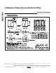
The MAX7445 filters and buffers video-encoder DAC
outputs in applications such as set-top boxes, hard-
disk recorders, DVD players, and digital VCRs. The
MAX7445 reconstructs and cleans up analog video sig-
nals from the output of DAC video encoders. Each
channel consists of a lowpass filter and an output video
buffer that can drive two standard 150Ω video loads.
This device operates from a single +5V supply and has
a nominal cutoff frequency of 5MHz optimized for
NTSC, PAL, and SDTV.
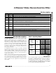
The MAX7445 has three modes of operation allowing
different video signals to be processed. The modes are
shown in Table 1. Mode 1 requires that channel A is a
video signal that includes a sync pulse. A sync separa-
tor uses this signal to extract the timing required to
clamp all four channels.
Modes 2 and 3 require that channel A and channel D
have a sync pulse to provide the required timing informa-
tion. Channel A provides the required timing for channels
A, B, and C while channel D provides its own sync sepa-
rator to extract the sync signal from an asynchronous
video signal.
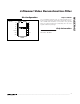
Filter
Filter Response
The reconstruction filter consists of two 2nd-order Sallen-
Key stages. The Butterworth-type response features a
maximally flat passband for NTSC and PAL bandwidths.
The stopband offers at least 43dB (typ) of attenuation at
a video-encoder DAC sampling frequency of 27MHz
(see the Typical Operating Characteristics).
MODE SELECT CHANNEL SIGNAL
A CVBS
BR
CG
MODE 1
CVBS/RGB
GND
DB
A CVBS
BY
CC
MODE 2
CVBS/Y/C/
CVBS
ASYNC
V
CC
D CVBS
ASYNC
A G (with sync)
BR
CB
MODE 3
RGB/CVBS
ASYNC
(G with sync)
FLOATING
D CVBS
ASYNC
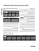
PIN NAME FUNCTION
1 INA Channel A Video Input. AC-couple INA with a series 0.1µF capacitor.
2 INB Channel B Video Input. AC-couple INB with a series 0.1µF capacitor.
3 INC Channel C Video Input. AC-couple INC with a series 0.1µF capacitor.
4 IND Channel D Video Input. AC-couple IND with a series 0.1µF capacitor.
5 DISABLE
Disable Logic Input. A logic-low on DISABLE enables the output buffers. A logic-high on DISABLE disables
all output buffers and puts them in a high-impedance state.
6, 8 GND Ground
7 GAIN
Gain-Control Input. Connect GAIN to GND for a gain of +6dB (+2V/V), to V
CC
for a gain of +9.5dB (+3V/V),
or leave unconnected for a gain of +12dB (+4V/V).
9 SELECT
Mode Select Input. Connect to GND for CVBS/RGB processing, to V
CC
for CVBS/Y/C/CVBS
ASYNC
processing, or leave floating for RGB/CVBS
ASYNC
(G with sync) processing.
10 V
CC
+5V Supply Input
11 OUTD Channel D Video Output. This output can be either AC- or DC-coupled.
12 OUTC Channel C Video Output. This output can be either AC- or DC-coupled.
13 OUTB Channel B Video Output. This output can be either AC- or DC-coupled.
14 OUTA Channel A Video Output. This output can be either AC- or DC-coupled.
Pin Description
Table 1. Operating Modes