
Manual


I
2
C-Interfaced Key-Switch Controller and LED
Driver/GPIOs with Integrated ESD Protection
MAX7360
______________________________________________________________________________________ 29
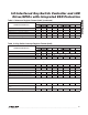
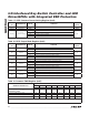
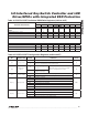
Table 24. PORT0–PORT7 Individual PWM Ratio Registers (0x50 to 0x57)
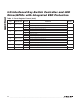
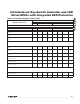
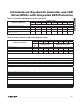
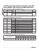
Table 25. PORT0–PORT7 Configuration Registers (0x58 to 0x5F)
REGISTER DESCRIPTION
REGISTER DATA
D7 D6 D5 D4 D3 D2 D1 D0
PORT PWM
Power-up default setting (port PWM ratio is
0/256)
0 0 0 0 0 0 0 0
PORT PWM ratio is 1/256 0 0 0 0 0 0 0 1
PORT PWM ratio is 2/256 0 0 0 0 0 0 1 0
PORT PWM ratio is 3/256 0 0 0 0 0 0 1 1
.
.
.
PORT PWM ratio is 252/256 1 1 1 1 1 1 0 0
PORT PWM ratio is 253/256 1 1 1 1 1 1 0 1
PORT PWM ratio is 254/256 1 1 1 1 1 1 1 0
PORT PWM ratio is 256/256 (100% duty cycle)
1 1 1 1 1 1 1 1
REGISTER
BIT
DESCRIPTION VALUE FUNCTION
DEFAULT
VALUE
D7 Interrupt mask
0 Interrupt is not masked
0
1
Interrupt is masked. PORT7 interrupt mask is ignored when the
device is configured for rotary switch input.
D6
Edge/level
detect
0
Rising edge-triggered
interrupts
Interrupts only occur when the GPIO
port is configured as an input
0
1
Rising or falling edge-
triggered interrupts
D5 Common PWM
0 Port uses individual PWM intensity register to set the PWM ratio
0
1 Port uses common PWM intensity register to set the PWM ratio
D[4:2] Blink period
000 Port does not blink
000
001 Port blink period is 256ms
010 Port blink period is 512ms
011 Port blink period is 1024ms
100 Port blink period is 2048ms
101 Port blink period is 4096ms
110/111 Undefined
D[1:0] Blink-on time
00 LED is on for 50% of the blink period
00
01 LED is on for 25% of the blink period
10 LED is on for 12.5% of the blink period
11 LED is on for 6.25% of the blink period