
Manual


I
2
C-Interfaced Key-Switch Controller and LED
Driver/GPIOs with Integrated ESD Protection
MAX7360
28 _____________________________________________________________________________________
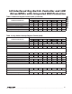
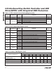
Table 21. I
2
C Timeout Flag Register (0x48) (Read Only)
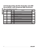
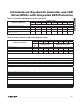
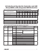
Table 22. GPIO Input Register (0x49) (Read Only)
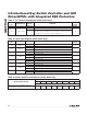
Table 23. Rotary Switch Count Register (0x4A) (Read Only)
REGISTER
BIT
DESCRIPTION VALUE FUNCTION
DEFAULT
VALUE
D[7:1] Reserved 0000000 — 0000000
D0
I
2
C timeout flag
0
No I
2
C timeout has occurred since last read or POR
0
1
I
2
C timeout has occurred since last read or POR. This bit is reset to
zero when a read is performed on this register. I
2
C timeouts must
be enabled for this function to work (see Table 8).
REGISTER DESCRIPTION
REGISTER DATA
D7 D6 D5 D4 D3 D2 D1 D0
CYCLE COUNT
Cycle count in two’s complement (see the
Rotary Switch Configuration (0x46) section)
X X X X X X X X
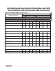
REGISTER
BIT
DESCRIPTION VALUE FUNCTION
DEFAULT
VALUE
D7 PORT7
0 Port is input low
0
1 Port is input high
D6 PORT6
0 Port is input low
0
1 Port is input high
D5 PORT5
0 Port is input low
0
1 Port is input high
D4 PORT4
0 Port is input low
0
1 Port is input high
D3 PORT3
0 Port is input low
0
1 Port is input high
D2 PORT2
0 Port is input low
0
1 Port is input high
D1 PORT1
0 Port is input low
0
1 Port is input high
D0 PORT0
0 Port is input low
0
1 Port is input high