
Manual


I
2
C-Interfaced Key-Switch Controller and LED
Driver/GPIOs with Integrated ESD Protection
MAX7360
26 _____________________________________________________________________________________
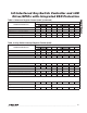
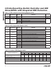
Table 17. GPIO Constant-Current Setting Register (0x43)
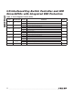
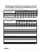
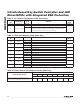
Table 18. GPIO Output Mode Register (0x44)
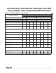
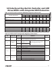
Table 19. Common PWM Register (0x45)
REGISTER
BIT
DESCRIPTION VALUE FUNCTION
DEFAULT
VALUE
D[7:6] Reserved 11 Set always as 11 11
D[5:2] Reserved 0000 — 0000
D[1:0]
Constant-
current setting
00 Constant current is 5mA
00
01 Constant current is 6.67mA
10 Constant current is 10mA
11 Constant current is 20mA
REGISTER
BIT
DESCRIPTION VALUE FUNCTION
DEFAULT
VALUE
D7 PORT7
0 Port is a constant-current open-drain output
0
1 Port is a non-constant-current open-drain output
D6 PORT6
0 Port is a constant-current open-drain output
0
1 Port is a non-constant-current open-drain output
D5 PORT5
0 Port is a constant-current open-drain output
0
1 Port is a non-constant-current open-drain output
D4 PORT4
0 Port is a constant-current open-drain output
0
1 Port is a non-constant-current open-drain output
D3 PORT3
0 Port is a constant-current open-drain output
0
1 Port is a non-constant-current open-drain output
D2 PORT2
0 Port is a constant-current open-drain output
0
1 Port is a non-constant-current open-drain output
D1 PORT1
0 Port is a constant-current open-drain output
0
1 Port is a non-constant-current open-drain output
D0 PORT0
0 Port is a constant-current open-drain output
0
1 Port is a non-constant-current open-drain output
REGISTER DESCRIPTION
REGISTER DATA
D7 D6 D5 D4 D3 D2 D1 D0
COMMON PWM
Power-up default setting (common
PWM ratio is 0/256)
0 0 0 0 0 0 0 0
Common PWM ratio is 1/256 0 0 0 0 0 0 0 1
Common PWM ratio is 2/256 0 0 0 0 0 0 1 0
Common PWM ratio is 3/256 0 0 0 0 0 0 1 1
.
.
.