
Manual


I
2
C-Interfaced Key-Switch Controller and LED
Driver/GPIOs with Integrated ESD Protection
MAX7360
24 _____________________________________________________________________________________
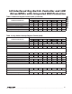
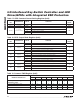
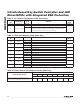
Table 13. Autosleep Register Format (0x06)
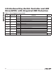
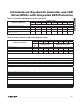
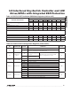
Table 14. GPIO Global Configuration Register (0x40)
REGISTER REGISTER DATA
AUTOSLEEP REGISTER
RESERVED AUTOSHUTDOWN TIME
D7 D6 D5 D4 D3 D2 D1 D0
No Autosleep 0 0 0 0 0 0 0 0
Autosleep for (ms)
8192 0 0 0 0 0 0 0 1
4096 0 0 0 0 0 0 1 0
2048 0 0 0 0 0 0 1 1
1024 0 0 0 0 0 1 0 0
512 0 0 0 0 0 1 0 1
256 0 0 0 0 0 1 1 0
256 0 0 0 0 0 1 1 1
Power-up default settings 0 0 0 0 0 1 1 1
REGISTER
BIT
DESCRIPTION VALUE FUNCTION
DEFAULT
VALUE
D7
PORT6/PORT7
rotary switch
0 PORT6/PORT7 operate as GPIOs
0
1 PORT6/PORT7 operate as a rotary switch input
D6 Reserved 0 — 0
D5
I
2
C timeout
interrupt
enable
0 Disabled
0
1
INTI is asserted when I
2
C bus times out. INTI is deasserted when a
read is performed on the I
2
C timeout flag register (0x48).
D4 GPIO enable
0
PWM, constant-current circuits, and GPIs are shut down. GPO
values depend on their setting. Register 0x41 to 0x5F values are
stored and cannot be changed. The entire part is shut down if the
key switches are in sleep mode (D7 of register 0x01).
0
1
Normal GPIO operation. PWM, constant-current circuits, and GPIOs are
enabled regardless of key-switch sleep mode state (see Table 8).
D3 GPIO reset
0 Normal operation
0
1
Return all GPIO registers (registers 0x40 to 0x5F) to their POR value.
This bit is momentary and resets itself to 0 after the write cycle.
D[2:0]
Fade in/out
time
000 No fading
000
XXX
PWM intensity ramps up (down) between the common PWM value
and 0% duty cycle in 16 steps over the following time period:
D[2:0] = 001 = 256ms
D[2:0] = 010 = 512ms
D[2:0] = 011 = 1024ms
D[2:0] = 100 = 2048ms
D[2:0] = 101 = 4096ms
D[2:0] = 110/111 = Undefined